AN1092 - Driving Reactive Loads with High Frequency Op-Amps
Although pure capacitive loads are rare at high frequencies, this does not mean that we can ignore them. Capacitive reactance can exist over narrow frequency ranges, and we must ensure that our amplifier does not oscillate in these ranges.
Capacitive Loads are Hard
Generally, an op-amp has no problem driving resistive or inductive loads. Of course, this statement needs to be qualified as to the size of the load, but the point is that both kinds of loads do not degrade the phase margin of the amplifier. Capacitive loads, on the other hand, do reduce an amplifier's phase margin, and in severe cases can cause the op-amp to oscillate.
External Compensation—The Snubber
Another way to stabilize an op-amp driving a capacitive load is the use of a snubber, as shown in Figure 3D. To see how a snubber can reduce peaking, consider the 300MHz ƒT transistor presented in Section 2. For that example, the output inductance of the emitter follower was shown to be 100nH. With a light resistive load RL = 1kΩ and moderate capacitive load CL = 50pF, the circuit resonates at 70MHz with a Q g
In this case, Q works out to be about 22, giving us severe peaking in the frequency response. However, with a load of 150Ω, the Q reduces to 3. Thus the extra stability gained with a heavy load resistor is desirable, but we may be wasting DC load current with this approach. A way around this is to insert a capacitor in series with the resistor, resulting in a snubber. There are various ways to determine appropriate values for RSNUB and CSNUB, one of which is presented in [2].
We will describe an alternative method here. First, operate the amplifier as in the intended application and look at its frequency response on a network analyzer. Find the frequency at which the peak occurs, and denote that as ƒp. Next, try loading the amplifier with different load resistances until the peaking reduces to a satisfactory level; this value will be RSNUB. Finally, we need a capacitor that will make the snubber look resistive at the frequency of the peak. A rough guideline is to make the snubber zero frequency 3 times lower than ƒp, resulting in the following design equation:
Note that as opposed to the series resistor method, the use of a snubber does not degrade the gain accuracy or cause extra distortion when driving a nonlinear load.
Nabla is more that that, it stands for 3 operators depending of the nature of the operand. It is a neat trick that enables to write, memorize and manipulate differential equations encountered in several fields of physics.
I was under the impression that Maxwell's wrote his equations down in straight differential form, and it was Heaviside who then put them in their current Nabla form.
I may be wrong on this - can't remember where I read it.
According to Wikipedia:Originally posted by Bonsai >
"can't remember where I read it."
The three field operators called gradient, divergenge and curl can each be expressed in terms of the Nabla vector operator.Maxwell's formulation of electromagnetism consisted of 20 equations in 20 variables. Heaviside employed the curl and divergence operators of the vector calculus to reformulate 12 of these 20 equations into four equations in four variables, the form by which they have been known ever since.
Don't know about you, but all this mathematics is enough to make my hair curl! 🙂
So for optimal results should the R of the zobel match the actual DCR of the speaker being used (including wires)
Last edited:
The "legendary" John, with high divergence ?The three field operators called gradient, divergenge and curl
Well linked! 🙂The "legendary" John, with high divergence ?
However, if we try to include gradient, we may be on a slippery slope!
Usually, one become to be legendary long after his death.Well linked! 🙂
However, if we try to include gradient, we may be on a slippery slope!
Next generations, taking on the job of forging the legend.
It must be a double punishment to have to build one's own, during one's lifetime, for the benefit of promoters who see there the opportunity to pay less copyright. (The legendary characters are not registered, by habit, as patent owners, see what I mean ?. And wax makes, in general, the slope even more slippery. Not easy to climb it when you're still clinging to it.)
That's what I thought about when I visited the Parasound website.
La Fontaine's fable "The raven and the fox".
I apologize for this personal remark which is all, except malevolent.
Last edited:
I am not seeing consensus in explanations.So for optimal results should the R of the zobel match the actual DCR of the speaker being used (including wires)
One purpose of the network is to ensure the amp has a defined load at ultrasonic frequencies where the cable/load effective impedance may have a rising inductive impedance characteristic.
A capacitively coupled low load resistance (4R7, 5R6,10R) is supplied across the amp terminals at high frequencies.
Amplifiers increase distortion with increased load (lower R) and increasing frequency, why is 20R or higher not suitable or standard ?.
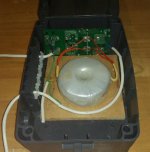
My latest AC power lead-free death trap machine....weeks in the thinking, an hour in the making lol.


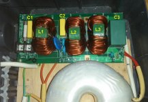
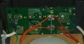
Screened isolation transformer is connected between L2 and L3 which were originally directly connected.
I have selection of Wima Red type capacitors in 0.22uF and 10uF.
Is it useful to connect these caps or RC networks across the primary or secondary connections ?.
Why would the filter board originally have L2 and L3 series (like L1 to L2 ) connected but without shunt components ?.
Quick listen says system sounds clearer.
The secondary is isolated and foil shielded, is it it necessary to extend the incoming PE to the output socket ?.
Last edited:
Just as comment, a few months ago when I was writing up the Ground Loop presentation (link below) I took some toroidal transformers and measured the bandwidth CM and SM. In SM (is normal operating mode) the bandwidth on a 1.2kVA was 60 kHz and in common mode, it was flat to the limit of my generator (3MHz) - the latter expected since just capacitive coupling across the primary and secondary (1.2 nF without the screen connected, < 100 pF with it connected). A 500 VA transformer also exhibited very wide BW in both CM and SM.
Upshot is, you need some good filtering to keep WB garbage out of your amp circuits. I use one of these power line network extender things, and it pushes all sorts of garbage out on the line.
Upshot is, you need some good filtering to keep WB garbage out of your amp circuits. I use one of these power line network extender things, and it pushes all sorts of garbage out on the line.
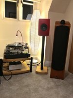
Lorin Maazel’s Sibelius 5th on the turntable plus a massive glass of red wine.
Attachments
Last edited:
I think this is right.I was under the impression that Maxwell's wrote his equations down in straight differential form, and it was Heaviside who then put them in their current Nabla form.
I may be wrong on this - can't remember where I read it.
Maxwell equations do not need the Nabla, it only comes in as a convenience.
AFAIK Hamilton is the father of the Nabla. Maxwell did use other math works from Hamilton.
These maths and physics interleaved, because things were in the air, science was pregnant for outcomes.
There is.a lot of excitement about Einstein, however science was pregnant too with work from Pointecarré and Lorentz.
You now, what ? I wish history of science should be seriously taught in school.
I wish history of science should be seriously taught in school.
And philosophy of science?
The philosophy of science
Philosophy of science - Wikipedia
Last edited:
Philosophy Of Science was a required course to get a BSEE at my uni in the 1970s.
Phlogiston == bad ; or at least, that's what they were teaching at the time.
Phlogiston == bad ; or at least, that's what they were teaching at the time.
Indeed, philosophy of science as I see defined in Wikipekia.
Trouble is, this philosophy is controversial, arguable with ideologies and religions.
OTOH, history of sciences is 100% facts, no belief, no intention, just facts ( all the rest is bound to BS and will be )
One might ask your definitions of philosophy and science, but it would already be asking you to enter into a philosophical approach.Trouble is, this philosophy is controversial, arguable with ideologies and religions.
Last edited:
Lorin Maazel’s Sibelius 5th on the turntable plus a massive glass of red wine.
You actually have one of those over the top TT's? I have two of the major Zuccarelli holophonic recordings on LP and use them with HD650 headphones to evaluate phono setups. I just have to say the U-turn turntable and $75 Grado black with my DIY phono stage offers as much listening pleasure as my far more expensive setups in the past. All the fuss no longer has any value to me, MHO of course.
Last edited:
Just as comment, a few months ago when I was writing up the Ground Loop presentation (link below) I took some toroidal transformers and measured the bandwidth CM and SM. In SM (is normal operating mode) the bandwidth on a 1.2kVA was 60 kHz and in common mode, it was flat to the limit of my generator (3MHz) - the latter expected since just capacitive coupling across the primary and secondary (1.2 nF without the screen connected, < 100 pF with it connected). A 500 VA transformer also exhibited very wide BW in both CM and SM.
Upshot is, you need some good filtering to keep WB garbage out of your amp circuits. I use one of these power line network extender things, and it pushes all sorts of garbage out on the line.
In the US under the most common electrical code you can have several volts between safety ground terminals. Last I looked the unofficial test was that it had to blow a 20 amp fuse from a 120 volt hot lead.
The theory is that all safety ground wires are connected via local branch isolated busses to the mains power entrance breaker box where they are connected to the grounding system and neutral.
In most residences there is a single breaker box. So the safety ground differences should be only from capacitive leakage current in the cable runs. In my slightly larger projects the safety ground differences can be more than 6 volts from one equipment room to another.
I took a two term course in the 'History of Science and Technology' during my first year at university.You now, what ? I wish history of science should be seriously taught in school.
I spent so much time formulating my essay on the development of genetics that I failed my maths exam! 😀
You actually have one of those over the top TT's? I have two of the major Zuccarelli holophonic recordings on LP and use them with HD650 headphones to evaluate phono setups. I just have to say the U-turn turntable and $75 Grado black with my DIY phono stage offers as much listening pleasure as my far more expensive setups in the past. All the fuss no longer has any value to me, MHO of course.
Nah - not over the top. It’s a Michel - 1980 design that got it right first time and its never changed. The arm is a 35 year old SME I got off eBay in perfect nick.
- Status
- Not open for further replies.
- Home
- Member Areas
- The Lounge
- John Curl's Blowtorch preamplifier part III
