One issue might be related to something like AD797 in the context of ESS 'hump' distortion removal.
AFAIK JC has not designed any DAC's.
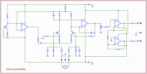
Those series ferrites in conjunction with the bridging yellow cap are an AC filter.Dan,
I suppose it would prudent to understand why the little ferrites are there before removing them and replacing with twisted wire and if that would cause detrimental effects somewhere else.
I am not certain where in the supply these ferrites are....likely feeding the relay stage power supply but maybe feeding the main transformer also, either way IME the presence of ferrites in the AC circuit causes 'ferrite sound' and I have removed exactly these kinds of ferrites in the past with only beneficial effects.
Power supply wiring schematic please ?.JC......anyone?
I find the 99.3Sn/0.7Cu wets and tins like lead solder only the temp is critical and near to toasting the flux.And would something like the quad eutectic be easier for a beginner, because research points to 99.3/.7 being a pita to use?
Wires and connectors should be pre-tinned with cleaned solder.....a cloth and tiny bit of alcohol is sufficient to polish the oxides from the solder wire immediately prior to use and should be done at every solder usage.
The WBT is Lead/Tin with 4% Silver.......this is the worst of alloys IMO/IME, I would not use it.
Sure the joints tin and flow beautifully and are brightly shiny but IMO lead and silver do not go together at all and the sound caused is all wrong.
Bob, the boards are now lead-free, do yourself a favour and keep it that way, ie keep all lead right out of the Hint.
If you want to be adventurous you can build interconnects with different solder alloys and audition for yourself, IME different alloys sound different and I quite like the 99.3/0.7.....slightly 'polite' sounding perhaps but never 'hard' or 'brash' sounding like some alloys.
Dan.
Last edited:
Riiiight.I like the AIM with Silver and use it for prototypes. The lead free is for production.
Nope......it's not lead-free.I’ve used (and have some) WBT 0800 and liked working with it.......is it good?
Dan.
This is the recipe that Panasonic uses, with Panasonic Part No.
Dan.RFKZ03D01K-----------(0.3mm 100g Reel)
RFKZ06D01K-----------(0.6mm 100g Reel)
RFKZ10D01K-----------(1.0mm 100g Reel)
Note * Ingredient: tin (Sn) 96.5%, silver (Ag) 3.0%, Copper (Cu) 0.5%, Cobalt (Co) / Germanium (Ge) 0.1 to 0.3%
AD797
This is the main reason why I posted my question on AD797, to JC.
Can you hear a difference between 2 solid state preamps?
The result (and my conclusion) in the linked thread and post is similar to my private listening tests with my visitors that I collected during 15+ years.
Thank you for searching the old posts on AD797, indra1. I have read them, earlier. Also thanks for JC comments. However, I was rather interested in more detailed description of sound of the chip, as it can be done, IME. This is also related to another thread and I will bring my long term impressions quite soon, in two weeks latest.
This is the main reason why I posted my question on AD797, to JC.
Can you hear a difference between 2 solid state preamps?
The result (and my conclusion) in the linked thread and post is similar to my private listening tests with my visitors that I collected during 15+ years.
interesting ADC... https://www.ti.com/product/TLV320ADC5140
and, an interesting review!!
Pass ACA Class A Power Amplifier Review | Audio Science Review (ASR) Forum
and, an interesting review!!
Pass ACA Class A Power Amplifier Review | Audio Science Review (ASR) Forum
Last edited:
Riiiight.
Nope......it's not lead-free.
Dan.
WBT 0805 is lead free Roth’s compliant....melting point 426 F
How about that?
This is the main reason why I posted my question on AD797, to JC.
Can you hear a difference between 2 solid state preamps?
The result (and my conclusion) in the linked thread and post is similar to my private listening tests with my visitors that I collected during 15+ years.
Very interesting conclusion. Jan Didden found in a listening experiment that the (small number of) participants preferred bandwidth limited to below 15kHz. When I combine this it all makes sense. FM radio could sound better than the original.
If my memory serves me correctly, John Siau (Benchmark) indicated the ESS 'hump' distortion was mostly attributed to CM distortion and careful matching of the post I-V phase summing stage was the solution.
Siau used LME49860 running on +-18v rails. Don't know sensitivity to dac output DC offset.
The article at ASR talks about removing the DC offset at the output of the dac before it gets to the differential-summing/balanced-MFB-filter stage (or balanced SK filter, in some designs). That seems to work fine for OPA1612.
Don't know if removing the dac output DC bias in the I/V stage is something that AD797 is best suited for.
Last edited:
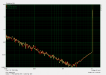
Anyone has any link or measurement that would show that AD797 has issues with HF CMV when driven from DAC output? Just this afternoon I measured the preamp with balanced input driven from balanced DAC output. The preamp has 2x2SK170BL followed by the opamp - AD797. The circuit is in fact the one posted by Scott W here a few years ago (thank you Scott). I measured THD and DIN IMD vs. level, covering almost full input range. Output is scaled by the stepped attenuator to match ADC input max. level. I can see neither THD, nor IMD "hump" as seen in
ESS THD ‘Hump’ Investigation | Audio Science Review (ASR) Forum
and I doubt the opamp is the reason of the hump.
Swapping AD797 for AD744 gives almost identical overlapping plots, that are completely determined by DAC/ADC parameters. Not by those of the opamps in the preamp. I think that once again some fairy tales are created here, that would be certainly appreciated as "open minded" by some members 😉. Without any proof, as almost always.
P.S.: my measurements show flat 80dB CMR within 20Hz-20kHz with this preamp, without special selection of resistors, just took 1% metal film types from the same batch.
Attachments

Last edited:
Anyone has any link or measurement that would show that AD797 has issues with HF CMV when driven from DAC output?
Most R&D into DAC circuitry optimization is proprietary. ESS even makes its customers sign NDAs to help keep secrets. I would like be able to describe a trick of Jam's I used to make AK4499 eval board circuitry sound better than AKM apparently could do, but the trick isn't my IP.
That looks to be equivalent to Multicore 96SC lead-free, yes it's worth a listen.WBT 0805 is lead free Roth’s compliant....melting point 426 F
How about that?
Dan.
I think the objection is likely not too much bandwidth so much as lowered THD/IMD products.Very interesting conclusion. Jan Didden found in a listening experiment that the (small number of) participants preferred bandwidth limited to below 15kHz. When I combine this it all makes sense. FM radio could sound better than the original.
Dan.
This is the recipe that Panasonic uses, with Panasonic Part No.Dan.
Anybody have ideas on why the Germanium and Cobalt in the mix ?.Note * Ingredient: tin (Sn) 96.5%, silver (Ag) 3.0%, Copper (Cu) 0.5%, Cobalt (Co) / Germanium (Ge) 0.1 to 0.3%
Dan.
I would guess corrosion resistance and improved hardening. Plus it will look nicer. lead free solders can produce some nasty looking joints even when they are fine.
I should remind people at this point that Martin Colloms, award winning speaker designer, author and general subjective flag waver thinks lead free solder is the worst thing to have happened to audio in decades. He actually had some amplifier boards made up with tin/lead and lead free to compare. I'll Take Mine Unleaded | Stereophile.com
I should remind people at this point that Martin Colloms, award winning speaker designer, author and general subjective flag waver thinks lead free solder is the worst thing to have happened to audio in decades. He actually had some amplifier boards made up with tin/lead and lead free to compare. I'll Take Mine Unleaded | Stereophile.com
...those numbers add up to more than 100%?Anybody have ideas on why...
Anybody have ideas on why the Germanium and Cobalt in the mix ?.
Cobalt provides a very strong sound and Germanium is known for lowering the soldering junction electron barrier.
Otherwise said, elementary my dear Watson: bait for Audiophools.
Real answer: those are unavoidable impurities in the alloy. Some consider worth mentioning, some don't.
Last edited:
Anybody have ideas on why the Germanium and Cobalt in the mix ?.
Go to the “Conclusions” for a short answer
(wettability and avoidance of solder bridging for Germanium, controlled nucleation and grain refinement for Cobalt)
Germanium
https://www.kester.com/Portals/0/Do...r alloy_Hasnine.pdf?ver=2017-07-24-145900-637
Cobalt
https://core.ac.uk/download/pdf/77013051.pdf
George
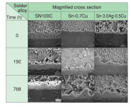
Thats looks like silver free Hihon Superior SN100c
●The trace addition of Ni means fewer shorts and no shrinkage defects
●Ni-stabilised intermetallic layer inhibits copper erosion
●Reliable in harsh environments
●High ductility ensure long service life of joints subjected to cyclic strain
●SN100C is formulated for minimal generation of dross.
Effect of Germanium on secondary lead-free tin solders
James
●The trace addition of Ni means fewer shorts and no shrinkage defects
●Ni-stabilised intermetallic layer inhibits copper erosion
●Reliable in harsh environments
●High ductility ensure long service life of joints subjected to cyclic strain
●SN100C is formulated for minimal generation of dross.
Effect of Germanium on secondary lead-free tin solders
germanium in lead-free solders reduces the formation of oxides on the surface by the addition of 0.01 wt. % Ge to the batch. With the amount of 0.01 wt. % also the grain is refined in the microstructure, resulting in improved castability. In terms of solderability experiments confirmed that germanium improves the flowability of solder on the PCB substrate
James
Attachments
Last edited:
- Status
- Not open for further replies.
- Home
- Member Areas
- The Lounge
- John Curl's Blowtorch preamplifier part III