Z source??
I see speakers tending towards trying to fix non linearities using entities which in themselves introduce problems. Shorting rings may help Le(x) but at the cost of rapidly increasing position based resistance (which I note never seems to be measured). I never see any analysis of the shorting ring L/R break frequency, no discussion of what frequency Le(x) is measured (someone here pointed that out). My belief is that speakers need to have magnetics capable of at least 50 kHz (iron laminations .1mm Max), non conductive formers, symmetrical magnetics, pole tip and front plate EDM gaps, and should be either current driven or Jn drive. My issue with current drive is, I've been in the field where I push the daylights out of the speakers, so cannot afford thermal runaway. My issue with Jn drive, is the added complexity of the cabling, speaker, and slightly more complex electronics.
Jn
Last edited:
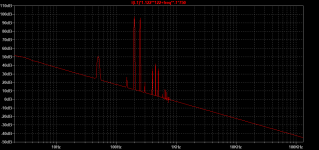
Here are PMA's measurements of intermodulation at 200+250Hz:
John Curl's Blowtorch preamplifier part III
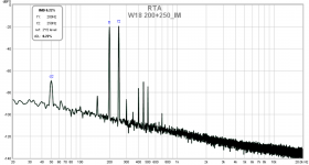
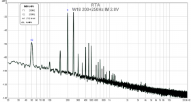
I rebuilt my speaker model to be slightly more modular but missing some features. I finally figured out a way to parameterize the reluctance force without affecting anything else. Attached are similar plots to PMA's measurements.
The majority of the distortion in PMA's plots appears to come from reluctance force and is 2nd harmonics. The 3rd harmonics aren't explained by reluctance force and for them I used very basic BL(x) modeling. These are only 2 distortions included in the model to get this result.
John Curl's Blowtorch preamplifier part III
I rebuilt my speaker model to be slightly more modular but missing some features. I finally figured out a way to parameterize the reluctance force without affecting anything else. Attached are similar plots to PMA's measurements.
The majority of the distortion in PMA's plots appears to come from reluctance force and is 2nd harmonics. The 3rd harmonics aren't explained by reluctance force and for them I used very basic BL(x) modeling. These are only 2 distortions included in the model to get this result.
Attachments
I can lend you my copy his _Acoustical Engineering_. Just PM me a shipping address.Still can't find Olson in a Google search though.
All good fortune,
Chris
Might be useful to remove cone from motor. measure without reflections/influence of the edge suspension et al.
A with and without.
-RNM
A with and without.
-RNM
Last edited:
This guy found a fascinating machine "sitting in the corner" of a university hallway. Download the PDF and watch all four videos on your biggest high-res monitor!
Albert Michelson's Harmonic Analyzer (book details))
<snip>
Personally I have just been working on making parametric functions that can model the curves I see in Klippel analyzer data. John Curl posted a page from Olson that showed a good basic function for Kms(x). Still can't find Olson in a Google search though.
At least two of his books (dynamical analogies and elements of acoustical engineering) are available for download at the archive.org website.
@RNMarsh,
sure COMSOL would help, but is unfortunately quite expensive (haven't checked if personal use licenses are offered) , means > 4,000 $ , I think DPH could tell more about it's advantages and drawbacks.
Therefore I linked the open source package Elmer, which is also cappable and due to it's university basis a solid approach and will presumably not stop in development for the future.
Not that easy to use, but getting good results isn't that easy with COMSOL either, steep learning curve required. 🙂
Here are PMA's measurements of intermodulation at 200+250Hz:
John Curl's Blowtorch preamplifier part III
I rebuilt my speaker model to be slightly more modular but missing some features. I finally figured out a way to parameterize the reluctance force without affecting anything else. Attached are similar plots to PMA's measurements.
The majority of the distortion in PMA's plots appears to come from reluctance force and is 2nd harmonics. The 3rd harmonics aren't explained by reluctance force and for them I used very basic BL(x) modeling. These are only 2 distortions included in the model to get this result.
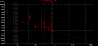
Interesting. For comparison, IMD measurements of a new speaker design I am about to finish. Measured in noisy environment, going to book anechoic room shortly for fine tuning and proper measurements. So far, so good.


Here are PMA's measurements of intermodulation at 200+250Hz:
John Curl's Blowtorch preamplifier part III
I rebuilt my speaker model to be slightly more modular but missing some features. I finally figured out a way to parameterize the reluctance force without affecting anything else. Attached are similar plots to PMA's measurements.
The majority of the distortion in PMA's plots appears to come from reluctance force and is 2nd harmonics. The 3rd harmonics aren't explained by reluctance force and for them I used very basic BL(x) modeling. These are only 2 distortions included in the model to get this result.
Looks like very good approximation, I think you speak about the attached measurements:
Attachments
measured up close to driver? What about normal power level which would be used for same spl at 3-4 meters away in listening room (10W or more)? Every speaker can look better when speaker has very little power into it.
-RNM
-RNM
Last edited:
My measurements were done at loud listening level, but precise level set measurements will follow once in anechoic environment. Measuring distance around 1 meter.
Pavel, we cross posted it seems with something very similar 🙂
Pavel, we cross posted it seems with something very similar 🙂
measured up close to driver? What about normal power level which would be used for same spl at 3-4 meters away in listening room (10W or more)? Every speaker can look better when speaker has very little power into it.
-RNM
No anechoic chamber at my place. Measurement of distortion in a farfield in a room is a nonsense, as was many times explained. So please stop repeating your request.
Thanks for the offer. I'd love to have the physical book, but I think I'll make do with the online scans.I can lend you my copy his _Acoustical Engineering_. Just PM me a shipping address.
All good fortune,
Chris
Richard, the problem with far field measurements of distortion in a room is not just noise, it is also room modes. The microphone I use can handle 140 dB without distortion, so even relatively close up, I can test loud without microphone artifacts.
I've also had some observations on distortion behavior at the bass resonance that may well relate to yours. What I have found is that distortion has a minimum at some drive impedance that is in proportion to the motional impedance of the speaker. The effect seems to get stronger with increasing driver size, but in small drivers it has been hardly observable.RNMarsh said:I am a little surprised the electronic brains here couldnt describe the operation which causes THD to be lowered though. Such an old concept. I am not sure those implementing the concept really understand why, either.
My explanation is simply that the Bl(x) nonlinearity becomes partially canceled due to the counteracting Bl errors in the back-EMF voltage and the Bli force. According to this theory, the optimum condition is achieved when the back-EMF voltage (Blv) equals the resistive voltage drop Ri where R includes the amp output resistance. Then, when Bl falls e.g. by 10%, the Bli force would otherwise also exhibit a similar fall, BUT at the same time, the Blv voltage component also exhibits the same 10% decrease, so that the Ri voltage and the current gets increased by the 10%, thus canceling most of the effect of the Bl variation.
Farther from the resonance peak(s), the cancellation diminishes as Blv decreases and turns its phase. It might be possible to tailor the output impedance accordingly to widen the area of distortion reduction, but I haven't studied this further.
You need to find a way to get it done. Close measurements are totally unrealistic. Not characteristic of what you will hear; Measure one thing, hear another. Little value to perceptions.No anechoic chamber at my place. Measurement of distortion in a farfield in a room is a nonsense, as was many times explained. So please stop repeating your request.
Find an anechoic lab and use it. At minimum do as vacuphile suggests he can do tests at realistic power input to driver with the microphone he has. I suggest using at least 10W input as more realistic.
THx-RNMarsh
Last edited:
Aren't they just higher SPL?Close measurements are totally unrealistic.
Are you going to pay for Pavels time or are you just ordering people about to do your work?Find an anechoic lab and use it.
THx-RNMarsh
😀 😎I've also had some observations on distortion behavior at the bass resonance that may well relate to yours. What I have found is that distortion has a minimum at some drive impedance that is in proportion to the motional impedance of the speaker. The effect seems to get stronger with increasing driver size, but in small drivers it has been hardly observable.
My explanation is simply that the Bl(x) nonlinearity becomes partially canceled due to the counteracting Bl errors in the back-EMF voltage and the Bli force. According to this theory, the optimum condition is achieved when the back-EMF voltage (Blv) equals the resistive voltage drop Ri where R includes the amp output resistance. Then, when Bl falls e.g. by 10%, the Bli force would otherwise also exhibit a similar fall, BUT at the same time, the Blv voltage component also exhibits the same 10% decrease, so that the Ri voltage and the current gets increased by the 10%, thus canceling most of the effect of the Bl variation.
Farther from the resonance peak(s), the cancellation diminishes as Blv decreases and turns its phase. It might be possible to tailor the output impedance accordingly to widen the area of distortion reduction, but I haven't studied this further.
yes. I dont know the details as described but, yes for bass only seems to work best. Around resonance. Your desciption of what is happening is an interesting one. It is right to the point of what I had been doing some years (decades) ago. I hope this gets some traction here with others.
I cannot do anything about improving drivers, so i tried the current-mode mod. But, if Now we can do better with drivers that would be a real step forward.
Thank you for your contribution. It helps validate my intuition based upon tests and measurments. It may also give insight for others about how to reduce driver distortion.
Thx-RNMarsh
Richard, the problem with far field measurements of distortion in a room is not just noise, it is also room modes. The microphone I use can handle 140 dB without distortion, so even relatively close up, I can test loud without microphone artifacts.
of course it is the room modes. An out door environment is better. A anechoic chamber better yet.
Many proper tests can and are being done out side. Have been since forever.
easily found on internet now --->
An alternative is to simply lay the speaker on its back pointing at the sky on open grass. Ground reflection will still interfere, but will be greatly reduced in the mid-range because most speakers are directional, and only radiate very low frequencies backwards. Putting absorbent material around the speaker will reduce mid-range ripple by absorbing rear radiation. At low frequencies, the ground reflection is always in-phase, so that the measured response will have increased bass, but this is what generally happens in a room anyway, where the rear wall and the floor both provide a similar effect. There is a good case therefore using such ‘half-space’ measurements, and aiming for a flat ‘half-space’ response. Speakers that are equalised to give a flat ‘free-space’ response, will always sound very bass-heavy indoors, which is why monitor speakers tend to incorporate ‘half-space’, and ‘quarter-space’ (for corner use) settings which bring in attenuation below about 400 Hz.
Digging a hole and burying the speaker flush with the ground allows far more accurate half-space measurement, creating the loudspeaker equivalent of the boundary effect microphone (all reflections precisely in-phase) but any rear port must remain unblocked, and any rear mounted amplifier must be allowed cooling air. Diffraction from the edges of the enclosure are reduced, creating a repeatable and accurate, but not very representative, response curve."
These small signal tests of distortion (=/< 1W) needs to stop. It gives an overly optimistic result/impression. Large signal analysis is needed and shows in most cases very different results from the loudspeakers.
THx-RNMarsh
An overview on correct measurements proceedures without an anechoic chamber..... some more on out side loudspeaker testing:
Ground Plane Measurements for optimiziing an loudspeaker
Subwoofer Measurement Tactics: A Brief, Topical Overview & Method Comparison | Audioholics
This is by no means a detailed treatise of the subject. For a more in-depth treatment of this topic the reader is encouraged to read through the resources listed in the bibliography.
ETC
THx-RNMarsh
Last edited:
- Status
- Not open for further replies.
- Home
- Member Areas
- The Lounge
- John Curl's Blowtorch preamplifier part III