Could be useful, Current Source Amplifiers and Full Range Drivers article by Nelson Pass from 2004.... I may try to repeat the experiment, sometimes.
Last edited:
Yes. A pair of Audio-Pro B4-200 made for a quite impressive demonstration. I sold the whole range in the late -70.
//
//
Thank you Dimitri, the two tone stuff is pretty clear. I'll try to blow up some of the figures so I can see more detail of what was done.
There is a relevant thread “Simple MFB woofer project” here:
Simple MFB woofer project
The first post of this thread has lost it’s images (external host). A good guy has archived this first post here:
diyAudio Forums Archive - Simple MFB woofer project
ACE BASS is implemented in Audio-Pro subs. Google for service manuals. (e.g. B2-50 )
George
Simple MFB woofer project
The first post of this thread has lost it’s images (external host). A good guy has archived this first post here:
diyAudio Forums Archive - Simple MFB woofer project
ACE BASS is implemented in Audio-Pro subs. Google for service manuals. (e.g. B2-50 )
George
For John Curl:
With a modest 400VA toroidal transformer, two 35A bridge rectifier modules in the GBPC package, and 60 millifarads/rail times two rails, here's the inrush when all countermeasures are defeated by shorting wires. Click image to see it full size.
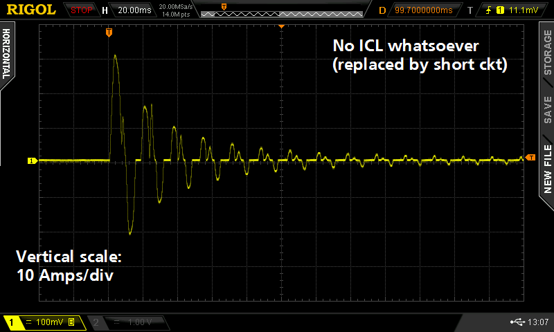
With a modest 400VA toroidal transformer, two 35A bridge rectifier modules in the GBPC package, and 60 millifarads/rail times two rails, here's the inrush when all countermeasures are defeated by shorting wires. Click image to see it full size.
Mark,
Try measuring the AC power source resistance. Simple to do. Measure open circuit voltage and then use something like a clothes iron for a load. Current draw and voltage drop will yield AC power line source impedance.
Next we can talk about AC power line protection typical limits. Incandescent light bulbs when failing often draw a surge of ten times normal load current. As a result the protection is designed not to trip under those conditions.
Last edited:
Not interested. If anyone else IS interested, please go right ahead! And please accept my best wishes and fond hopes for gigantic, immediate success.
Not interested. If anyone else IS interested, please go right ahead! And please accept my best wishes and fond hopes for gigantic, immediate success.
I'm confused I though we were talking about speakers?😕
I am sorry you are confused.
I'm sorry no one is interested.
I am sorry you are confused.
I will admit, when you posted that inrush current waveform for the 100 watt lightbulb, it didn't seem to be consistent with any discussion I saw.
I do note, you mentioned seconds with respect to bulb thermal settling, yet your scope photo showed setting in roughly 6 or 7 cycles, which is about 100 milliseconds.
Is there a diode surge current discussion going on? I actually know sumptin bout that stuff, having been an application engineer for the largest manufacturer of Kbpc bridges on the planet..back in 84.
Jn
Last edited:
Actually, I think that Mark had hoped that I would respond, since we talked about this test by phone, earilier. I was just as confused by what I saw. Thanks JN, for bringing up the confusing parts of Mark's input. From what I saw, I could not make much of it, in terms of blowing fuses and such. Mark, perhaps you should make your questions a bit more clear.
Mark- 30A peak is not abnormal. I have seen consistent 100A peak currents on initial start. A Toroid transformer shut down at the right part of the cycle can look like a dead short and take out SB fuses. The power line needs to be quite robust to not have lots of nuisance breaker trips etc. PS Audio learned the hard way just how nasty many electronic loads can be. Crest factors of 10 are not unusual. And they put a real burden on distribution equipment. One of the driving factors behind power factor correction requirements on new electronics.
What is abnormal is the second current peak on the positive side. It looks more like an SCR regulator than what you would expect from a simple supply. Is there on one power supply in the box? Are there other rectifier-cap combinations tied to the supplies fed by a 1/2 wave rectifier?
A quick fix for an amplifier with toroidal transformer that occasionally trips the fuse switch during turn on or turn off is to power it through an inductance formed by some loops of a flexible extension cord.
And always retighten the wire attaching screws at the wall sockets and at the fuse panel. They tend to break loose (intimate contact), worsening the turn on/off impulse current issue
George
And always retighten the wire attaching screws at the wall sockets and at the fuse panel. They tend to break loose (intimate contact), worsening the turn on/off impulse current issue
George
The spikes are why I suggested Mark check his line impedance. They are typical of a bad line. Often due to loose screws or even spring compression outlet connectors or corrosion if aluminum wiring.
toroidal transformer that occasionally trips the fuse switch during turn on
which is inevitable for a bigger toroidal transformer, because the initial inrush current peak depend on instant input voltage phase when you switch on the amp. The peak is always different and sometimes it trips the home breaker. The only cure is inrush-limiter circuit, which starts with inserted resistance that is shorted after several half-periods of the mains current by a relay. This is a pure and working and reliable solution.
The only cure is inrush-limiter circuit, which starts with inserted resistance that is shorted after several half-periods of the mains current by a relay. This is a pure and working and reliable solution.
Yes.
The easy fix is for the "don't open the lid" cases 😀
George
No questions really; just thought JC might be interested in viewing a bit of detail on a couple of inrush waveforms after chatting about the topic on the phone. Posted here in case anyone else might be interested to see: What does the peak look like, how long does it take to die out, what sort of peak-to-average ratios might occur, that kind of thing. BTW thanks everyone for the speculations & thoughts about the waveshape abnormalities on the toroid 30A inrush photo; as you might suppose, it is a "before" picture. The "after" pictures vary depending upon which countermeasure is selected, but all of them are boring to look at. They are exactly what you'd expect, differing only in the height of the peak and the rate of decay afterwards.
After a quick survey of test instrumentation that allows you to specify the phase angle of the AC mains where turn-on should occur, I decided the price was far higher than I was willing to spend on this little two afternoon lab frolic. So I built myself a rig that turns on at the worst case angle if you assume "ELI the ICE man" is the only enemy. About 10 dollars worth of parts on a 20 dollar PCB.
After a quick survey of test instrumentation that allows you to specify the phase angle of the AC mains where turn-on should occur, I decided the price was far higher than I was willing to spend on this little two afternoon lab frolic. So I built myself a rig that turns on at the worst case angle if you assume "ELI the ICE man" is the only enemy. About 10 dollars worth of parts on a 20 dollar PCB.
- Status
- Not open for further replies.
- Home
- Member Areas
- The Lounge
- John Curl's Blowtorch preamplifier part III