folded cascode vs. dual differential, and low capacitance vs. low noise
There is a discussion at the Kaneda thread about folded cascode vs. dual differential. kaneda preamp
Jonathan Carr seems to be avocating folded cascode. But I remember John using dual differential in his JC2 phono. Perhaps he can educate us on the two different approaches.
Also there was a discussion at the same thread on the virtues of low capacitance JFETs (e.g. 2SK30ATM) vs low noise as input LTP (e.g. 2SK170). It was said : "To design deliberately for lowest noise would mean extending the bandwidth as little as possible and using the lowest-noise devices available. Ultra-low-noise devices almost always have large surface areas and quite a bit of capacitance. Along with lower noise, the result would be less resolution (and the smaller bandwidth).
In contrast to the above, I try for very low intermodulation with very wide bandwidth, and try to get the noise as low as possible within that framework. This way, the resolution and phase response will be excellent, and even if there is noise, it will be decoded in a different manner from the musical signal, and should therefore be very easy to ignore. I personally think that the latter approach does less damage to the music than designing for the lowest possible noise floor."
I wonder if you may have a different opinion ?
Thanks in advance, Patrick
I wonder if you may have a different opinion ?
Thanks in advance,
Patrick
I think intelligent discussion of these issues is lost in the dross. I have some new idea's to replace that in-amp in my signal chain. Something to try, little ventured for whatever gain. Make up your own mind.
If you are looking for an in-amp for audio, maybe you would like this ?
https://www.diyaudio.com/forums/ana...d-single-converter-revisited.html#post5596866
😉
Patrick
https://www.diyaudio.com/forums/ana...d-single-converter-revisited.html#post5596866
😉
Patrick
I think intelligent discussion of these issues is lost in the dross. I have some new idea's to replace that in-amp in my signal chain. Something to try, little ventured for whatever gain. Make up your own mind.
Ironically I thought your use of the in-amp in your balanced phono design was one of the (but by no means only) interesting parts of the design. It seemed to provide a lot of flexbility and simplicity. What is the source of your urge to ditch it? (By all means scratch that itch, just curious why.)
PS: I never built that circuit, but it is on my "one of these days" list, even though I would need to do some TT rewiring.
Attachments
Ironically I thought your use of the in-amp in your balanced phono design was one of the (but by no means only) interesting parts of the design.
Just to keep it discrete all the way, and Patrick asked if I dumped the 8-legs. 🙂 I'll see if I can get the schematic up soon and then I might just add it at the end of the other thread. Warning it's simple and cheap (unless of course you buy matched FET's on eBay) and no double differential wizz bang just a cute trick.
I can't build it right now to give it a real try (or get back to my M2) but this situation I'm in will end and we will move into a nice new place before Christmas.
EDIT - Patrick, I agree on the use of the biggest low noise JFET's not being appropriate to every application. I fought this for years, people would take apart those tiny microphone capsules (destroying several in the process) to solder in 2SK170's. A total waste of time and money. Building an 0.5nV amplifier for a 1K source impedance makes little sense, that should be obvious.
Last edited:
Happy for you. Hope everything works out as expected now.... will move into a nice new place before Christmas....
Share it with the plebs
George
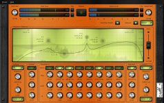
It is just a set of ingredients at the moment to experiment with. The focusrite Scarlett 6i6 is to get audio in and out as it has both analog and SPDIF in and out, so I can get a digital feed to the miniDSP. Calf Studio Calf Studio Gear - GNU/Linux Audio Plug-Ins has some nice midi controllable equalisers than don't require a DAW to have running. And a midi control box.
The theory is that I can put ubuntu studio on an old laptop and, once setup should allow me to sit on the sofa and twiddle settings. the eq will do both channels, or L, R, M,S seperately which allows me to play with things before working out what is actually useful. With some thought should be able to dial in a loudness curve (static) that suits me.
IF it all plays nicely together! Can you tell I always wanted a cello palette 🙂
The best thing about this solution is the number of sensibilities it will offend...
Attachments


EUVL, you ask an interesting question. The 'very best' solution in some cases is to use BOTH topologies at the same time. This is how the Blowtorch preamp is designed.
However, my second choice is to use the complementary differential jfet input topolology in 4 quadrant operation, as I am doing with a new power amp that I am designing. Third position is 2 quadrant complementary differential, or the folded cascode differential input with a current mirror as a 'turn around' circuit after the cascode. It is a toss up between these two.
When it comes to jfets, I still tend to use 2SK170-J74 pairs because my customers usually have them in stock. However, some of the 'long gate' lower capacitance complementary jfets made by Linear Systems look interesting, but they have LOW transconductance, and this can be a problem. Still, the low capacitance and the convenient choice of complementary matched pairs of both N and P channel devices makes it a viable choice in some instances, just not for ultra low noise applications.
John,
The topology they were talking about in the Kaneda thread is similar to the OPA1632 schematics, but with N-JFET input and a current mirror at the 2nd stage to convert to single ended output. I find this more difficult to get to unity gain stability compared to the JC2 Phono type topology, using existing Toshiba devices and same relatively low bias.
As to input JFETs, we all use 2SK170/2SJ74 when we have them, without really thinking. But the most interesting input devices I have found is the 2SK163/2SJ44 pair, unfortunately obsolete for quite a while. They are both low noise, have reasonable transconductance (~10ms), but have low capacitance (Crss 3pF & 10pF).
I guess you would agree that if source impedance is high (e.g. Sallen Key filters), a single NJFET input would have lower capacitance and thus lower distortion at high frequencies ? And the 2SK117/2SK209 from Toshiba has the highest Yfs/capacitance ratio among them all. And the latter (SMD) is actually still active.
Cheers,
Patrick
.
Attachments
Been away for a while, off designing a new power supply pcb for an old Pioneer SX-1980 receiver, nice to see that Toshiba jfets are still topics of conversation 🙂
Transistors | Products | Toshiba Electronic Devices & Storage Corporation | Americas – United States
To bad Toshiba does not think the same as you folks, in that their is a market worth consideration for p-ch jfets. As far Toshiba is concerned, probably know where near enough volume to justify the product. Markets/revenue drive products.
Hi John,
it begs the ?, roughly how many Toshiba jfets does your customer hold in inventory? 100's, 1000's? Obviously a limiting factor in product volumes. Lucky for you that the parts do not have shelf life 🙂
As I see it, the products that you design incur a sizable NRE charge as part of the product cost, unless you are doing it just for fun 🙂
I do wonder why Linear Systems could not make the ls k170/j74 exactly the same as Toshiba parts? that is if the lower trans-conductance is so important. has this feedback been sent to LS? I do wonder if they think it is an issue with the adoption of their product since you are not endorsing them in your designs?
Rick
I assume you are referring to only n-ch jfets.And the 2SK117/2SK209 from Toshiba has the highest Yfs/capacitance ratio among them all. And the latter (SMD) is actually still active.
Transistors | Products | Toshiba Electronic Devices & Storage Corporation | Americas – United States
To bad Toshiba does not think the same as you folks, in that their is a market worth consideration for p-ch jfets. As far Toshiba is concerned, probably know where near enough volume to justify the product. Markets/revenue drive products.
Hi John,
it begs the ?, roughly how many Toshiba jfets does your customer hold in inventory? 100's, 1000's? Obviously a limiting factor in product volumes. Lucky for you that the parts do not have shelf life 🙂
As I see it, the products that you design incur a sizable NRE charge as part of the product cost, unless you are doing it just for fun 🙂
I do wonder why Linear Systems could not make the ls k170/j74 exactly the same as Toshiba parts? that is if the lower trans-conductance is so important. has this feedback been sent to LS? I do wonder if they think it is an issue with the adoption of their product since you are not endorsing them in your designs?
Rick
I guess you would agree that if source impedance is high (e.g. Sallen Key filters), a single NJFET input would have lower capacitance and thus lower distortion at high frequencies?.
The SK filters I am familiar with all have a relatively low impedance at
high frequencies, provided either by the series or shunt capacitors,
so I don't imagine the Jfet capacitance to be an issue there.
John,
The topology they were talking about in the Kaneda thread is similar to the OPA1632 schematics, but with N-JFET input and a current mirror at the 2nd stage to convert to single ended output.
.
This is similar to my "three-legged" op-amp (never published). Think of bringing the common mode feedback all the way to the base of a third input device. It was the highest performance DSL driver in terms of quiescent to output power ratio we ever did, one customer asked why we bothered with 3 power modes the lowest got full rate and reach. It was VFB all the way but used a complementary CFP output stage.
I do wonder why Linear Systems could not make the ls k170/j74 exactly the same as Toshiba parts? that is if the lower trans-conductance is so important. has this feedback been sent to LS? I do wonder if they think it is an issue with the adoption of their product since you are not endorsing them in your designs?
Rick
It has been brought up, IMO too much focus on Idss and not the beta (transconductance) parameter. It's easy to find cheap switching FET's with crazy Idss but >3V Vp's. Frankly the first date code of LSJ74 had Idss at the expense of high Vp so the gm (noise) in your circuits would suffer, the second batch was much better.
At least it is recognized that the gm to C ratio is important since some of these special FET's are simply massively paralleled on the die. I posted a 2SK170 pic here that makes that clear. So an option is to parallel then in your circuit as many have done.
Distortion Reduction in Moving-Coil Loudspeaker Systems Using Current-Drive Technology.
by P.G.L. Mills and M.O.J. Hawksford.
JAES Vol.37, No.3 1989 March
-RNM
by P.G.L. Mills and M.O.J. Hawksford.
JAES Vol.37, No.3 1989 March
-RNM
I do impedance compensation since decades in all my speaker's assemblies. With great audible improvement.It's a two-step thing. Yes, the passive crossover can be both a problem and a blessing. The whole thing is about finding a remedy, you are spot on about that. The more series impedance you have with the back-EMF impedance of the driver, the more it will be suppressed, but the key word here is series because it forces the impedance upwards (step 1) and that make the EQ of the amplifier much easier to do (step 2). So the crossover can work in your favour. This is exactly how the Elsinore Project DIY speakers works. But to do a crossover this way is a leap of faith because in your mind you have to change your priorities.
About bass speakers in bass reflex assembly, just a tip: If you compensate the resonance of the bass speaker in free air, you just have to tune the serial resistance once charged in bass reflex, and it will compensate the lower impedance peak in, the same time than the upper one around the resonance frequency...and you will get a flat impedance from DC up to the highest frequencies. Audible improvement in the dumping of bass frequencies.
Each of the drivers I use comes always with their own compensation circuit.
This way, we just have to *calculate* our passive filters, no need of "tuning" to adapt the curves to the impedance's curves of each of them at the crossover points.
Of course, the naysayers will not even try. They just follow the flock of sheep "politically correct habits". Who cares of their opinions ?
Of course too, we have to "break in" the speakers, before to measure them in order to calculate their compensation circuits, because they change a lot their Thiele/Small parameters during the first hours of use, before to stabilize.
Even amplifier side, there is a benefit: if you look at the feedback signal in the amp, you'll see less level when compensation circuits are "on". Less level means less distortion.
Last edited:
- Status
- Not open for further replies.
- Home
- Member Areas
- The Lounge
- John Curl's Blowtorch preamplifier part III