So, how would one go about measuring this signal induced 'jitter' ....what kind of signal and what kind of sensing ?.
Dan.
As a first pass, I would run say 2kHz into both channels, biased to one side with ITD and IID for image placement maybe 20 physical degrees right of a mono signal used for center reference. Then, toss a low bass signal hard on left. If the right signal drifts with respect to center reference, that's the smoking gun. Then it becomes, how to correlate? I would try xylophone hits as first pass. And, it may require a third center speaker for reference, that prevents bass on left from confounding reference location. And as I think of it, if a third speaker is reference, a mono signal could be the test, if the bass smears the mono off the third speaker reference, bingo. Also, the third can be moved off center and the test image signal with ITD and IID located at the reference. And, the test signal could just be panned to match reference location, as that is how much stereo content is placed anyhoo.
Jn
Last edited:
Then it becomes, how to correlate?
I would try xylophone hits as first pass. And, it may require a third center speaker for reference, that prevents bass on left from confounding reference location.
I assume you are talking electrical measurements here, in which case filtering the bass and analyzing the residual should be easy.
I would try a behavioral simulation to get some target numbers first. What would the set of L/R signals be to try one of these scenarios, frequencies, mag, and phase?
or to borrow a setup from tape flutter analysis. HF tone on L, hit R with LF pulses. (use zero crossing signal source) Demodulate HF tone and look for LF hits at the frequency of occurrence and pulse content in the FFT. Phase and Frequency demodulation could be used.
test with 8 ohm and simulated LS load.
does that give us a test to see if anything is "pulling" the signal?
Alan
test with 8 ohm and simulated LS load.
does that give us a test to see if anything is "pulling" the signal?
Alan
Last edited:
All good suggestions but what we are looking at something so far below tape and LP artifacts that I don't think this exercise is useful. I would suggest highly averaged and filtered data using the Hilbert transform to separate the AM and FM in software.
This is the equivalent to diff gain/diff phase for audio rather than video and the loop-gains available at audio frequencies are far higher than at 3.58MHz.
This is the equivalent to diff gain/diff phase for audio rather than video and the loop-gains available at audio frequencies are far higher than at 3.58MHz.
or to borrow a setup from tape flutter analysis. HF tone on L, hit R with LF pulses. (use zero crossing signal source) Demodulate HF tone and look for LF hits at the frequency of occurrence and pulse content in the FFT. Phase and Frequency demodulation could be used.
test with 8 ohm and simulated LS load.
does that give us a test to see if anything is "pulling" the signal?
Alan
what could be used to do the demod?
This test could give clue/predict the relative size and clarity of the image. Fuzzy, blury or sharp and focused, etc.
Might find a correlation.... psrr? especially with two channels powered by one supply. Imaging is often better with dual supplies or dual mono.
-Richard
All good suggestions but what we are looking at something so far below tape and LP artifacts that I don't think this exercise is useful. I would suggest highly averaged and filtered data using the Hilbert transform to separate the AM and FM in software.
This is the equivalent to diff gain/diff phase for audio rather than video and the loop-gains available at audio frequencies are far higher than at 3.58MHz.
How much phase change is expected to find? I can probably do it with equip I have.... dual channel network analyzer. 4 degrees? more?
-Richard
basic tests for diff gain/phase. Same for audio?
http://www.ti.com/lit/an/sloa040/sloa040.pdf
-RM
If there is time modulation you should not need a time difference to see it. Drive both channels with a mid band tone out of phase. Mix will cancel normally to some significant depth. Add other content to one channel, mix as above and look for modulating residual at the reference tone. A vintage wave analyzer would be up to this task. It would also remove any questions about the test setup compromising the measurement.
Hi Demian,
That sounds good also. Can you clarify more or a sketch of test layout/ Not sure what you mean add other content etc.
-Richard
That sounds good also. Can you clarify more or a sketch of test layout/ Not sure what you mean add other content etc.
-Richard
I would think the "other content" should be a signal that does not produce any HD/IMD components near the test tone, say, one octave left and right of the test tone. Then one can filter out the "other content" (linphase FIR bandstop) to isolate the test-tone residual.
To get a deep null to begin with, I'd use the same channel interleaved (other content on/off for a second, repeated forever), do time domain averaging to get the 2 seconds master block from some 1000 blocks or so, filter it (some caution needed here) and split it into its on/off sections, then subtract.
Doing this with no "other content" first gives a baseline null/noisefloor for the setup. Increase the other content signal strength and wait for something emerge from the noise floor that is correlated to the "other content".
I would also use a chopped test tone, a sequence of sine bursts with raised-cosine enevelope as this allows to identify the residual more readily, of course it must be, like any other signals used for this kind of test, repetitive with regard to the 1 second block lenght so that sync'd averaging will work.
Only a decent sound card is needed, the rest is software.
Then one can filter out the "other content" (linphase FIR bandstop) to isolate the test-tone residual.
It is useful to note that current compute power would allow brute force FFT filtering of test stimulus and data. Say something like a deep notch in 2min of music to embed a tone with a ~300dB numerical noise floor.
It is useful to note that current compute power would allow brute force FFT filtering of test stimulus and data. Say something like a deep notch in 2min of music to embed a tone with a ~300dB numerical noise floor.
If we were to time modulate a 5 kHz sine at a 40 hz rate, say 2.5 uSec delayed when primary negative, and 2.5 uSec advanced when primary positive, what exactly would the fft see? And, would we be looking for an amplitude dependent shift or a rate of change driven shift? Yah, it' only 90 degrees out, but the dependency would become frequency dependent. At least using signal processing removes the cone distance change error.
Are you sure 300 dB down is sufficient? I mean, some people have really good hearing..
I mean, a coulumb aint that many electrons, single ones might be audible....just sayin😉😉
Jn
Oh, and I do not think the circuitry per say would be the concern. Moreso wire and component coupling, coupling is ignored in spice.
Last edited:
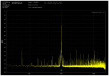
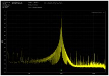
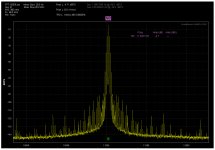
Last year I decided to test my self for jitter sensitivity with an interesting result, I'm not good to hear jitter. I took a CDP and replaced the xtal in the oscillator with a lower frequency one and than with an old Marconi RF generator with AM and FM modulation ability. Here's the 1kHz tone seen by the QA400 ,first with a wrong xtal and than the Marconi RF unmodulated. More to follow.
Attachments
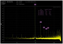
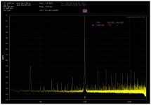
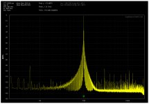
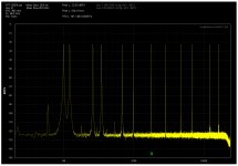
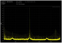
Here's 3 drastic examples of 1kHz signal effected with hight jittery oscillator.
First: I can't hear anything wrong
Second: I can barely hear it
Third: I can hear it
all using a headphone.
Still more to come.
First: I can't hear anything wrong
Second: I can barely hear it
Third: I can hear it
all using a headphone.
Still more to come.
Attachments

At last 3 pictures of Wakibaki's Jitter3, with the original xtal and with the Marconi modulated oscillator.
Attachments
Here's 3 drastic examples of 1kHz signal effected with hight jittery oscillator.
First: I can't hear anything wrong
Second: I can barely hear it
Third: I can hear it
all using a headphone.
Still more to come.
That's really interesting because the 'experts' here at DIYAudio, would say none of it is audible. Its all masked as within 2H. Hmmm.
However, I believe you hear what you have shown and reported. And could identify in blind random switch between #1 and #3. Which is what you would have to do to change minds of the self appointed "experts" here.
THx-RNMarsh
Last edited:
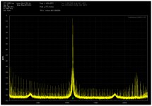
Here are the 12 tones with the Marconi, unmodulated and modulated ref oscillator.
Miklos, are you actually modulating 12 tones?
Maybe you mentioned it, in earlier post that I way
I ask now. Which 12 did you select and why?
and from the looks of it, well now I'm replying and
I can't see the FFTs.
Cheers,
That's really interesting because the 'experts' here at DIYAudio, would say none of it is audible. Its all masked as within 2H. Hmmm.
However, I believe you hear what you have shown and reported. And could identify in blind random switch between #1 and #3. Which is what you would have to do to change minds of the self appointed "experts" here.
THx-RNMarsh
That's cute, because it does more to say that well behaving stuff is inaudible to miklos versus a pretty ugly looking pair of plots I'd assume are quite audible. (Post 6312) Methinks it's worth your while to reread Julian Dunn's work on jitter and the j test.
nah. Not that involved or interested.... unless it leads to something I can do that improves my designs/system. Just poking fun at the nay Sayers who wont listen for themselves yet who say you cant hear this or that.
Some day... if I live long enough.... I'll get out my jitter measuring instrument and try it.
A test I would be interested in is one which shows any dynamic affect on imaging, as a few suggested. And what specifically will improve it.
Thx-RNMarsh
Some day... if I live long enough.... I'll get out my jitter measuring instrument and try it.
A test I would be interested in is one which shows any dynamic affect on imaging, as a few suggested. And what specifically will improve it.
Thx-RNMarsh
Last edited:
Well if you want to poke fun at naysayers, it might help when your poking isn't backfiring. 😉
That's really interesting because the 'experts' here at DIYAudio, would say none of it is audible. Its all masked as within 2H. Hmmm.
I'm with DPH, which experts said this and where?
- Status
- Not open for further replies.
- Home
- Member Areas
- The Lounge
- John Curl's Blowtorch preamplifier part III