Much modern 'higher education' isn't very high. Modern EE courses often have very little on circuit design, so a qualified EE may know less about circuits than a keen self-taught teenager. There will be exceptions, of course.Ultima Thule said:Higher educations still spits out so called "EE's" who haven't been drilled into paying attention to details, perhaps it's in some peoples nature and/or bad luck not having a real hands-on geeky teacher.
If a datasheet shows capacitance varying with applied voltage then it directly shows non-linear distortion in a coupling capacitor application; you can even estimate how much distortion.john curl said:I might point out that PMA's data sheet does not DIRECTLY infer non-linear distortion or DA (dielectric absorption) or linear distortion.
You can catch capacitor distortion with a simple sine wave measurement; in fact this is probably the easiest way to do it. Do I detect a hint of Fourier denial here?That is why the parts distributors will steer you to X7R or equivalent caps. They are cheaper, smaller, and available in large values, BUT they distort BADLY! But you will not necessarily easily catch their problem with a simple sine wave measurement, and trust me, you can destroy the sound quality of a remarkable design with just using X7R caps in a serious audio stage.
A 33uF electrolytic would do the job just fine.OK everybody, here is the Sony FM radio analog output using 2.2uF and 1uF caps. I would like to use COG (NPO) ceramics for this. Where do I find these caps?
This capacitor discussion is hopeless, as many other engineering topics in this thread. Same misleading generalizations again and again, together with irrelevant shots. I am leaving this.
Don't go Pavel. There's probably tons of lurkers out there that benefit from your and others' facts and figure posts.
Jan
Jan
I agree with Jan, and find your commentary a refreshing and necessary counterpoint to many of the comments here. Some of us are listening. I know it is frustrating, but I appreciate your thought provoking posts and the effort to set the record straight.
Or at least just wait this part of the discussion out and let things go dormant for a while. (IMO)
Didn't you threatened to bugger off yourself at one point Jan? 😉🙂 Just sayin', in the words of Dan 🙄
I know you did cuz I said I'd miss you and you got all embarrassed 😀
I know you did cuz I said I'd miss you and you got all embarrassed 😀
I am sorry that this has gotten so confused:
Let me try to explain the situation more clearly, so that it all makes sense.
1. Sony and many other mid-fi audio manufacturers need some sort of coupling cap for their output circuitry.
2. The usual output capacitance value is 1uF or greater. Why? Because the expected load impedance can be as low as 10K ohm.
3. With a 10K input, the low frequency response is 10K times 1uF, divided by 6.28 (or 2pi) This works out to about 16 Hz for a -3dB response. Probably OK for mid-fi, not for hi fi. Why would you want to put in a sub-woofer and then roll it off prematurely?
4. COG or NPO ceramic caps which are linear, only go to a maximum value of 0.1uf generally. Therefore, they would reduce the bass even more drastically, if used with a 10K load. In fact a 0.1uf cap and a 10K load would start to roll off at about 160Hz (-3dB). Therefore, a 0.1 ceramic NPO cap is not really practical to use, except in special situations, as a coupling cap.
5. Because NPO caps are not available above 0.1 uf generally, other ceramic caps are used instead, and these caps are generally very non-linear, but mid-fi manufacturers can get away with it. The non-linear ceramic caps look much the same as the linear caps, so they are often mistaken for linear caps.
PMA has measured one of these non-linear caps, just like I did 40 years ago, and he wanted to clue everybody in about it. Good for him!
By the way, I modified my Sony tuner with quality electrolytic caps several years ago now, I am just showing how 'impossible' it is to use COG ceramic caps as general purpose coupling devices, so all of you out there, thanks for your interest in solving the problem.
I suppose it makes sense to continually refer to Sony as "mid-fi", since they produce a comprehensive range from "lo-fi" to "hi-fi"......Just sayin
Didn't you threatened to bugger off yourself at one point Jan? 😉🙂 Just sayin', in the words of Dan 🙄
I know you did cuz I said I'd miss you and you got all embarrassed 😀
I might, long time ago before I discovered the joys of the ignore list 🙂
2. The usual output capacitance value is 1uF or greater. Why? Because the expected load impedance can be as low as 10K ohm. .
BS. The load on the circuit you showed is an emitter follower with a 1k Re. At least 100-200k.
3. With a 10K input, the low frequency response is 10K times 1uF, divided by 6.28 (or 2pi) This works out to about 16 Hz for a -3dB response. Probably OK for mid-fi, not for hi fi. Why would you want to put in a sub-woofer and then roll it off prematurely? .
We were talking about your precious SONY radio, not high-end.
4. COG or NPO ceramic caps which are linear, only go to a maximum value of 0.1uf generally. .
10uF, COG, 25V, $ 0.40 Mouser 603-CC1210MK5V7BB106
On and on. It's amazing how much BS one can pack in a single post.
Jan
10uF, COG, 25V, $ 0.40 Mouser 603-CC1210MK5V7BB106
To be fair: that part is new at Mouser and they're only stocking 4 parts that are C0G/NP0 in SMT > 1 uF. So let's rejoice that these parts are coming in but let's also be honest that it's a new development.
Yeah right. So we have to make do with 'only' 4.7u COG at 25V. OTOH, it's only $ 0.24. Then again, they only have 3000 in stock.
Ohh well.
Jan
603-CC0805MK7R8BB475
Ohh well.
Jan
603-CC0805MK7R8BB475
I'm just saying that these parts are "new at Mouser" -- John was right that historically C0G/NP0 didn't come in these sizes, and it looks like a move created by automotive demand! If you haven't been paying attention to what's being stocked in the past 6 months, it'd be easy to miss it. Goodness gracious Jan, calm down. On the corollary, it's great you pointed out that these parts *do* exist now, and can be used to good effect.
To be fair: that part is new at Mouser and they're only stocking 4 parts that are C0G/NP0 in SMT > 1 uF.
So let's rejoice that these parts are coming in but let's also be honest that it's a new development.
There is something fishy about this. The Mouser and mfr part numbers are different,
and the Mouser number omits the first letter of the dielectric code. The parts designated
as COG/NPO may be mistakes on Mouser's part. The mfr numbers for the parts mentioned
are for X7R or Y5V dielectrics.
Last edited:
Actually, as I'm looking at this more carefully, these are mislabeled y5v parts. Look at the DS and part code.
Edit -- agreed, Rayma!
Edit -- agreed, Rayma!
There's also the sanity check that a 1210 C0G would have to be a meter tall to be 10 uF.
Looks like the biggest in-stock C0G/NP0 at Mouser is 0.15 uF in a 2220 package.
Oh well, but good eye.
Looks like the biggest in-stock C0G/NP0 at Mouser is 0.15 uF in a 2220 package.
Oh well, but good eye.
> I modified my Sony tuner with quality electrolytic caps several years ago now,
Polarized or Non-Polarized ?
Polarized or Non-Polarized ?
Back on John's Sony Radio. It was $200 when new, $100 after a few years. I have no idea about FM HD as europe went 'NIH' and we got DAB. But the parts cost of this unit will have been low. It reviewed as one of the best sounding so either Steve Guttenberg is deaf or Sony did something right. Or both... Sony XDR-F1HD review: Sony XDR-F1HD - CNET
@traderbam
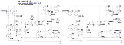
As promised here is another take on the error correction method we were talking about. This one is something you could actually build out of curiosity. It is a correction for the input to output voltage error on a simple diamond output stage which would include offset, crossover, thermal memory, and output resistance.
To illustrate things more clearly I turned this into a simple differential in to single ended open-loop amplifier. Using labels from the left circuit (the one with the EC "feedback"). I3 and I4 would represent differential input from an input transconductance via something like a folded cascode. The load would be R7 (10k) so a 1.0S gm would give you a gain of 10,000 (80dB). V3, F1, and E1 are an ideal representation of the bootstrapped current mirror which allows simulating everything without unreal negative components.
It is true that if you disconnect R8 from the output and use it as an input the current mirror chases its own tail and the circuit rails to one rail or the other, but connected as shown it is perfectly stable with perfectly matched components and ideal sources. Yes even if the diamond output is replaced with an ideal VCVS it is stable.
Stepping di (a delta in input current) from 100uA to -100uA the output roughly goes from 2V to -2V as expected. The right circuit without R8 has about .4dB gain error (almost exactly what you would expect from the 25 Ohm output resistance at 0V re: 600 Ohm load) and for a DC sweep the "S" shaped tanh Vbe error is seen (some call it gm doubling). The left circuit is perfectly linear within base current errors and the AC gain is exactly 80dB. The offset is accounted for also by the different betas on the N and P transistors.
The frequency response is modest due to the simple diamond, the input C and 10K limit it to about 3-4MHz. Which brings me to the point. If you inject a voltage into the loop, V4 (which represents an input to output voltage error) there is still 60dB of attenuation (at the output) of it at 800kHz. So the question is where does the effective GBW of 800MHz come from? No it's not somehow from making an ideal current mirror, you can actually disconnect R8 from the output and using it as an input catch the output at around 0V and do an AC analysis. The gain is around 60dB, I suppose because the transistor's bases are a DC load very slightly unbalancing the 10k's, and the GBW is the same 3-4MHz as the amplifier.
I'm actually going back toward defending the original statements. By conventional feedback thinking you have an error inside the loop you need loop gain to reduce it.
Attachments
- Status
- Not open for further replies.
- Home
- Member Areas
- The Lounge
- John Curl's Blowtorch preamplifier part III