Back on John's Sony Radio. It was $200 when new, $100 after a few years. I have no idea about FM HD as europe went 'NIH' and we got DAB. But the parts cost of this unit will have been low. It reviewed as one of the best sounding so either Steve Guttenberg is deaf or Sony did something right. Or both... Sony XDR-F1HD review: Sony XDR-F1HD - CNET
If I'm looking at the description in John's quoted text plus the circuit snipped, we're missing the entire output amplifier stage? And we don't know at all what the load is there. I mean it's not too shocking to see an x7r in that price point (which is far away from high end $$-wise), but it might also be just fine if the actual voltage across the cap is super low (high input impedance in the subsequent stage)
P.S. thanks for the description, Scott.
Last edited:
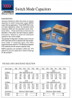
10uF, COG, 25V, $ 0.40 Mouser 603-CC1210MK5V7BB106
On and on. It's amazing how much BS one can pack in a single post.
Jan
Unfortunately this is the only cap that may even come close to fitting:
25V 1210 Rubycon Acrylic cap
25MU225MB23225 Rubycon | Capacitors | DigiKey
Johanson had 10u since a long time. I have given a pointer in this
thread a few years ago, but here the same s*** pops up again and again.
thread a few years ago, but here the same s*** pops up again and again.
While I agree it's been rehashed a million times over, there is no 10uF C0G/NPO dielectric cap that I can find from any manufacturer. It would be the size of a MKP cap anyway. Any part search suggesting otherwise is just a database issue.
There are lots of large MLCC using X7R and X5R though, I have used plenty of 1210 47uF X7R caps.
These are the largest C0G I have seen:
L1GN30C205KA10 KEMET | Capacitors | DigiKey
There are lots of large MLCC using X7R and X5R though, I have used plenty of 1210 47uF X7R caps.
These are the largest C0G I have seen:
L1GN30C205KA10 KEMET | Capacitors | DigiKey
At the time I developed the autoranger I used 0.15u at 250V, 5%. These were COG, at around $ 2.50. Size 2220.
https://www.mouser.be/ds/2/212/KEM_C1003_C0G_SMD-1101588.pdf
Jan
https://www.mouser.be/ds/2/212/KEM_C1003_C0G_SMD-1101588.pdf
Jan
Last edited:
Back on John's Sony Radio. It was $200 when new, $100 after a few years. I have no idea about FM HD as europe went 'NIH' and we got DAB. But the parts cost of this unit will have been low. It reviewed as one of the best sounding so either Steve Guttenberg is deaf or Sony did something right. Or both... Sony XDR-F1HD review: Sony XDR-F1HD - CNET
Exactly.
The BoM cost, including audio interconnects, wire aerial, owners manual, packaging etc, was an extravagant US$40.
Most of you would spend more than that on the front panel
You can use C0G if the right value for the context is available. That seems to be rather like most other component technologies. What is a 'general purpose coupling device?john curl said:By the way, I modified my Sony tuner with quality electrolytic caps several years ago now, I am just showing how 'impossible' it is to use COG ceramic caps as general purpose coupling devices, so all of you out there, thanks for your interest in solving the problem.
This capacitor discussion is hopeless, as many other engineering topics in this thread. Same misleading generalizations again and again, together with irrelevant shots. I am leaving this.
Please don't!
You're one of the few to provide actual modern measurements.

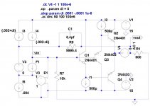
It's a TUNER DPH! The 2.2uF cap IS the output. By the way, it is a potentially GREAT TUNER. Millions must have been spent on Sony's development cost of the RF digital chip. Dick Sequerra himself recommended it to me as a high quality modern tuner.
I'm not sure I understand you. I would expect attenuation due to the bandwidth of the diamond buffer regardless of feedback.If you inject a voltage into the loop, V4 (which represents an input to output voltage error) there is still 60dB of attenuation (at the output) of it at 800kHz. So the question is where does the effective GBW of 800MHz come from?
You can measure the feedback loop gain by putting an AC voltage source in series with the 10k and mesuring the ratios of the voltages either side of it.
Sorry, for some reason I had in my head the clock radio (i.e. needing an OPS and a driver), even when looking at the image. Yeah a 2.2uf output cap could be unleashed upon a <10K input impedance pretty easily.
Not what you'd call "mid-fi"?It's a TUNER DPH! The 2.2uF cap IS the output. By the way, it is a potentially GREAT TUNER. Millions must have been spent on Sony's development cost of the RF digital chip. Dick Sequerra himself recommended it to me as a high quality modern tuner.
I'm not sure I understand you. I would expect attenuation due to the bandwidth of the diamond buffer regardless of feedback.
You can measure the feedback loop gain by putting an AC voltage source in series with the 10k and mesuring the ratios of the voltages either side of it.
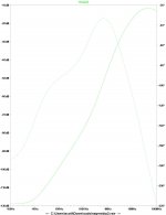
Sorry my last pictures were in error, the point where I injected the signal buffered the input impedance of the diamond buffer. I wondered why the balance did not need any tweek. It should have been at the output, so since this is an open loop circuit a source in series at the output appears unattenuated without R8 and C1 which are adjusted to compensate for the input impedance of the buffer (R8 is just slightly smaller and C1 is close to the input capacitance of the buffer). I included a plot of the AC output for a 0dB injected signal. The result is closer to what was expected (the 20dB/dec transitions into 40dB/decade at high frequencies).
The answer is the same, the signal at the output is attenuated by 78dB at 100kHz, by normal feedback arguments this is a GBW of 800MHz. I still argue the operation has more elements of balancing an AC bridge than feedback. Removing R8 and C1 gives 0dB flat at the output now. A better diamond buffer would be more useful because AC and DC input current errors are not nulled.
EDIT - The low frequency null is very touchy so in practice the 20dB/dec part of the plot tends to be hidden.
EDIT -
You can measure the feedback loop gain by putting an AC voltage source in series with the 10k and mesuring the ratios of the voltages either side of it
Not following you here driving the bottom of C7 with a source simply gives -.4dB at the other end rolled off by 10k and Cin as expected. C8 is equally unremarkable nothing that would indicate the net result.
Attachments
Last edited:
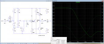
before I go to sleep here's a quick plot of the feedback loop gain. I think my circuit is the same as yours.Not following you here driving the bottom of C7 with a source simply gives -.4dB at the other end rolled off by 10k and Cin as expected. C8 is equally unremarkable nothing that would indicate the net result.
Attachments
It's a TUNER DPH! The 2.2uF cap IS the output. By the way, it is a potentially GREAT TUNER. Millions must have been spent on Sony's development cost of the RF digital chip. Dick Sequerra himself recommended it to me as a high quality modern tuner.
it IS an excellent tuner. I use it a lot. And, I have several other high quality tuners to compare.
THx-RNMarsh
before I go to sleep here's a quick plot of the feedback loop gain. I think my circuit is the same as yours.
That looks right 66 or so dB at low frequencies but the rejection ratio at DC is 120dB or so, more importantly I also forgot to mention that as you trim it goes through extreme rejection and back up the other side (like nulling a bridge). I might play some more tomorrow since we are about to be buried in snow again.
Last edited:
- Status
- Not open for further replies.
- Home
- Member Areas
- The Lounge
- John Curl's Blowtorch preamplifier part III