Slightly off topic, but in the world of 'dang thats impressive'. I note that the new Ishiny line has been launched with 7nm processors. That is close to witchcraft in my book.
You are welcome.
Figured out the immersion lithography many years ago. Bumped it up to bigwigs a long time ago.
They have not implemented the good stuff yet..
Time will tell.
Jn
haHaHa I am somewhere far south of Mexico city now. No one speaks english out here. But they have WiFi. and you guys still talking about same things .
Later ... they just had big party with music and fire works for the Independance day thing. but why so many police cars and all the windows have bars and chained pad locked doors?
Anyway, this is more fun. later, Its night time. I think i will go for a walk.. hope i dont get lost. Stinking hot and humid here.
oh ... update... my genius girl is now in sydney get signed up for university there for awhile and then to Canada. Math and science wiz. Only 19 and no experience in the outside world... She says its really different here. 🙂 Good thing she learns fast.
THx-RNMarsh
Last edited:
The signal chain is battery operated Laptop>USB Cable>USB Soundcard>RG59 Coax interconnects>Stereo Amplifier.There is a diagram in my gallery which shows the electrical equivalent of an IC and pc's forming a ground loop. The reactance so of each loop determine how the return current returns.
The only audio band signal path is the Interconnects.
At DC determined by the shield path total resistances, presumably near as dammit to equal (two same resistance braids and four same resistance connections).Two shielded IC's will split the DC return current 50/50.
Yes, the cable self current steering works against braid/connector resistance.When the frequency is high enough, the return current will be confined to the sending IC.
Given that clean RCA connectors measure around 20mOhms contact resistance, the same 1V amplitude signal on both interconnects and 10k ohms input impedance, what is the magnitude and effect on the signal of shield currents imbalance due to say 40mOhms contact resistance at one connector ?.
The cables are straight, 15mm apart and pretty parallel.Until that breakpoint, the return path will be very dependent on the physical arrangement of the two cables. Space them farther apart, the break frequency becomes lower.
What frequency range is to be expected for this breakpoint in RG59 ?.
Everything looks close to ideal to me, the only gross physical change is one cable direction.It is a confounder to any test of this type.
Dan.
You are welcome.
Figured out the immersion lithography many years ago. Bumped it up to bigwigs a long time ago.
They have not implemented the good stuff yet..
Time will tell.
Jn
EUV is really crazy stuff. The cost of the equipment is just staggering.
You didn't mention length.
Assume two rca's 40 milli.
Cable say shield of say 30 milli?
70 per shield. Bad connection say 90 total.
1.6 milli amps will split 700 micro amps on bad shield path, 900 on good shield path.
The cable impedance comes into play when the reactance of the alternat shield path is on the order of the coax impedance. If the coax is 50 ohms, when the inductance of the shield loop rises above 50 ohms, the return current will be happier in it's own coax.
Jn
Ok, I have stereo RCA cable connection from battery powered/floating DAC to AC mains powered amplifier.
What is the effect on the two audio signals of minor shield current imbalance ?.
Dan.
What is the effect on the two audio signals of minor shield current imbalance ?.
Dan.
It doesn't. It passes around a circuit of wire. Provided that the wire is fairly short (e.g. a domestic interconnect) you can use the low frequency approximation of electromagnetism, which we call circuit theory. The wire has series resistance, shunt capacitance and series inductance (which can sometimes be ignored). The resistance, which is highly linear, arises from well-known phenomena which can be considered either semi-classically or via quantum theory.john curl said:Personally, I still don't really know how an audio signal passes through a length of wire.
You can find the various parts of the theory in lots of textbooks. They won't talk about audio interconnects, because as being near-DC they are not very interesting to physicists. You may find the right answer unsatisfying; the universe can be like that sometimes!I have, for the last 25 years, tried to find the right textbooks that would give me a satisfying answer, but I have not found it yet.
I will have to leave it a bit vague. Undergraduate physics (early 1970s) said that the neutrino was massless. Possibly (not sure) postgraduate physics (later 1970s) said that it could have some mass because of neutrino oscillation, which was proposed as a solution to the Sun apparently not producing enough neutrinos but not believed by everyone back then. Later experiments confirmed this explanation.billshurv said:Define recently. I remember TW doing a correction on a report that the sun was about to go out and said that when they added neutrino mass it balanced out. That was mid 80s. So recent compared to relativity but not very recent?
Thicker conductor means any variations are averaged across much bigger area/more electrons so I would expect lower noise. I would expect most of the noise due to scattering to be already included in thermal noise, as scattering is the source of resistance and resistance is the source of thermal noise.simon7000 said:In my test measurements a single millimeter of .1 mm diameter cable has 1e22 or so copper atoms, each with 29 electrons. If we increase the diameter to 3 mm that is 900 times the atoms so there can be more variance in the path.
Add in some impurities the charges do not use for transit and the variation grows.
So what I think is happening is that thicker wire will appear to have more noise than thinner ones.
No. The AP is displaying raw data, as all instruments do. What that raw data means, and how this corresponds to real measurements, is a matter of interpretation. This depends on careful experimental design and careful experimental understanding. It is unfortunate that the availability of modern instrumentation means that raw data is getting easier and easier to obtain; actual measurements are just as hard as ever.simon7000 said:The AP is only displaying the test results.
So there is more than one mechanism causing resistance and noise at play ?.Thicker conductor means any variations are averaged across much bigger area/more electrons so I would expect lower noise. I would expect most of the noise due to scattering to be already included in thermal noise, as scattering is the source of resistance and resistance is the source of thermal noise.
What is the spectral nature of scattering and how does it influence total noise ?.
Is conductor noise totally white ?.
Dan.
I think we can assume that conductor noise is totally negligible.
Resistance is low, so thermal noise will be low.
Charge carriers are highly correlated in a good conductor so shot noise will be low.
People who measure tiny low frequency signals (gravity waves?) would be aware of any 1/f noise from wires. Perhaps you should ask them?
Resistance is low, so thermal noise will be low.
Charge carriers are highly correlated in a good conductor so shot noise will be low.
People who measure tiny low frequency signals (gravity waves?) would be aware of any 1/f noise from wires. Perhaps you should ask them?
Thicker conductor means any variations are averaged across much bigger area/more electrons so I would expect lower noise. I would expect most of the noise due to scattering to be already included in thermal noise, as scattering is the source of resistance and resistance is the source of thermal noise.
I think the issue is at higher currents that happens, but at extremely low currents there isn't as much interaction so the scattering may be more.
I did heat a copper wire to form oxides on the surface to see what effect that had. While hot it showed lots more energy in the target frequency band. Once it cooled it was the same.
George,
You are right reducing loop area reduces AC line pickup. If I roll up the cable that adds inductance, and if I fold it that would cause other problems often shown on a TDR.
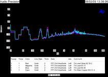
I have attached the original experiments on solder joints. This is what I consider to be the baseline of resolution. Note the noise floor through the filter establishes that. Not any real distortion difference between 200 solder joints of four different solders.
BTY the gizmo provides 56 dB of gain.
Chris,
I think you can see the difference between the baseline and the wire results.
Attachments
Last edited:
I thought of you smart people when I saw this IQ test question: (link).
Caution: naughty language in the comments
Lovely one.....
@scott wurcer,
Which are both to extreme points of view. A third questionable point would be to think that "sighted listening" is always "casual" .
Most people i know (different fields) that are using their senses for their work can´t do "blind tests" all the time. Instead they have to work around a lot of confounders.
Think for a moment about a test including everything as control available but without "blinding" and then the same setup but including "blinding" .
Would you really maintain the assertion that the first variant is only "casual" listening to please some folks (means the listener is only evaluating due to the bias introduced by knowledge about the DUT)?
While in the second variant the same listener suddenly is transformed into a biasless acting first rate evaluator?
If it were just the not knowing about the DUT the distraction level would imo much lower......
And we should remember the fact that this kind of distraction isn´t restricted to "golden ears" (when evaluating music stimuli) but whenever people are getting tested, be it tasting, smelling, responding to radar signals (SDT) .
@Mark4,
To lower the level of distraction i once tried to exclude the "participating in a test variable" by handing over just two of the same looking preamplifier boxes with different circuits and let them find out if they´d establish a preference.
The boxes were randomly marked and i find my preferred one out using the same procedure before.
For a positive result the other listeners had to choose the same circuit that i preferred.
Measured numbers for both circuits (according to the usual set) were well below the known thresholds.
Measurement were repeated after each return from the individual listeners.
Problems were that i had to find listeners, that i already knew and were routinely doing such kind of evaluations and more important would have the same kind of preference in case of this difference.
I could only find 5 matching the requirements so the sample size was small, below 5 it wouldn´t had made any sense due to the guessing probabilities.
Each listener got the boxes for a couple of days (the longest was two weeks) and when i came for taking the devices back he would tell me his preference choice (if any).
Turned out - after "deblinding" at the end - that all 5 indeed choosed the same and furthermore the same one that i preferred.
<snip> To me subjective is casual sighted listening is valid data for anything, to me it's just an exercise to make some folks happy.
Which are both to extreme points of view. A third questionable point would be to think that "sighted listening" is always "casual" .
Most people i know (different fields) that are using their senses for their work can´t do "blind tests" all the time. Instead they have to work around a lot of confounders.
Think for a moment about a test including everything as control available but without "blinding" and then the same setup but including "blinding" .
Would you really maintain the assertion that the first variant is only "casual" listening to please some folks (means the listener is only evaluating due to the bias introduced by knowledge about the DUT)?
While in the second variant the same listener suddenly is transformed into a biasless acting first rate evaluator?
As I said go for it whatever you want. The not knowing not peeking causes such stress in the ranks I never cease to be amazed.
If it were just the not knowing about the DUT the distraction level would imo much lower......
And we should remember the fact that this kind of distraction isn´t restricted to "golden ears" (when evaluating music stimuli) but whenever people are getting tested, be it tasting, smelling, responding to radar signals (SDT) .
@Mark4,
Understood and mostly agreed. I would like to see us fix that or at least substantially improve it.
To lower the level of distraction i once tried to exclude the "participating in a test variable" by handing over just two of the same looking preamplifier boxes with different circuits and let them find out if they´d establish a preference.
The boxes were randomly marked and i find my preferred one out using the same procedure before.
For a positive result the other listeners had to choose the same circuit that i preferred.
Measured numbers for both circuits (according to the usual set) were well below the known thresholds.
Measurement were repeated after each return from the individual listeners.
Problems were that i had to find listeners, that i already knew and were routinely doing such kind of evaluations and more important would have the same kind of preference in case of this difference.
I could only find 5 matching the requirements so the sample size was small, below 5 it wouldn´t had made any sense due to the guessing probabilities.
Each listener got the boxes for a couple of days (the longest was two weeks) and when i came for taking the devices back he would tell me his preference choice (if any).
Turned out - after "deblinding" at the end - that all 5 indeed choosed the same and furthermore the same one that i preferred.
I thought of you smart people when I saw this IQ test question: (link).
Caution: naughty language in the comments
Yes, excellent... I'm stuck in a loop now.... 😀
Turned out - after "deblinding" at the end...
Would you be willing to us how the blinding was performed, so you knew you didn't inadvertently influence the test subjects?
Thanks.
. If I roll up the cable that adds inductance, and if I fold it that would cause other problems often shown on a TDR.
Using the same length, one loop traps a specific area of flux, if you then make that wire two loops, it has one quarter the area but traps twice. The pickup of line noise will reduce by half.
If you place a solid ring conductor near the loop, it's eddy currents will fight flux intrusion, so will reduce pickup.
If you put a shielded cable in a looped length of 1/2 inch copper refridge tubing, and short the tubing at the ends, you will greatly diminish pickup. The only problem with that is it will alter the test if there is not full current cancellation between core and shield. For example, if the drive and receive connectors in the instrument are both tied to a common ground, not all the test current will return via the shield, but through the panel. Then, the coax under test will see the shorted turn of the copper pipe.
jn
edit. you can always do a figure 8, they will buck each other out.
Would you be willing to us how the blinding was performed, so you knew you didn't inadvertently influence the test subjects?
Thanks.
Someone else changed the labels so that i didn´t know about the relation when handing the boxes out.
This will get you started, note section 1 with no driving current you get the classic root(4KTR). You should look up Nyquist's own derivation of this, it is a wonderful piece of reasoning. Also note a lot of the research is on thin metal films on various substrates, not exactly ordinary wires.So there is more than one mechanism causing resistance and noise at play ?.
What is the spectral nature of scattering and how does it influence total noise ?.
Is conductor noise totally white ?.
Dan.
http://physics.princeton.edu/~mcdonald/examples/statistics/dutta_rmp_53_497_81.pdf
Since 90% of the so called audio improvements I read about on this web site are questionable to start with ( cables, "audio" caps, resistors, not to mention cable lifters and the really absurd) the first test should always be; can you hear a difference. I'm sure there out there. As in: a 5 throw switch where 4 of the contacts are connected to the same DUT and 1 is connected to the other DUT. If you can tell me which one is the different one 3 different times I'll believe you.
The other thing I would do, especially on people who think they can tell the difference between everything (plenty of those around here) is to do a blind test with no switching, always the same DUT. Will give you an indication of what to expect from them. ( constant guessing?)
The other thing I would do, especially on people who think they can tell the difference between everything (plenty of those around here) is to do a blind test with no switching, always the same DUT. Will give you an indication of what to expect from them. ( constant guessing?)
- Status
- Not open for further replies.
- Home
- Member Areas
- The Lounge
- John Curl's Blowtorch preamplifier part III