Scott,
I made a mistake. My average listening level is 52 dBc. Peaks seem to be no more than 15 dB above this. Currently playing Kingston Trio.
Chris,
Looking at the schematic, it seems the electrolytic 80 uF really doesn't affect much! But looking at spec sheets ESR seems about where it should be. As there is a 4 ohm resistor in series, even less effect than calculated before.
George,
Thanks.
ES
Last edited:
Destroyer,
1/4" isn't going to change a thing in comparison to the tweeter's directivity itself:
Baffle diffraction and roundover radius? -
Techtalk Speaker Building, Audio, Video Discussion Forum
Who gives a **** about the economics of effort? If that is your concern buy a $25 stereo from WalMart. This hobby is the existential epitome of diminishing returns.
I would thoroughly felt around the tweeter. That is very audible performance gain, very easy to get. You see it in some high designs like Wilson, but it is mostly overlooked.
If you haven't tried... try.
I don't get why the beligerence?
I simply stated that 1/4" roundover is purely a cosmetic thing, simple response to a shot from the hip comment.
I simply stated that 1/4" roundover is purely a cosmetic thing, simple response to a shot from the hip comment.
I don't get why the beligerence?
I simply stated that 1/4" roundover is purely a cosmetic thing, simple response to a shot from the hip comment.
Is that really you Derfy? The real one has hung out here long enought to know almost everyone here is an absolute expert. JC has been successful only due to dumb luck as so many here believe they know so much more.
I take it you didn't read or comprehend my reply.
Sorry I didn't disagree or invite an argument I just don't see the relevance to a piston radiating into half space. Observing the shock wave from a spark radiating into free space, the characteristic shape stops changing very soon.
The few litanies of ways for a speaker to distort I have seen only mention air nonlinearity with respect to horns. They show the distortion as due to the speed of sound varying with pressure and usually only treat the case of confinement in a tube or throat of a horn. Nelson did not specify all the conditions, the only reference I found was for active noise cancellation under special conditions, mufflers, factory ducts, etc. They gave 500Hz at 140dB SPL distorts ~1% for every meter in a duct.
If you have some interesting references please share them. I have measured a small cavity driven by a 3" woofer at 350Hz resonance @150dB SPL with a medical strain gauge pressure transducer and found 0.1% distortion but that was limited by the sensor.
I didn't say they were bad... It's just clear they're bleeding diffraction everywhere. It wouldn't be hard to just cut some boards 1/4" larger than the existing ones on the correct edges, then give them 1/4" round overs. In a few places you might have to stick some absorbing material. Doing that might take them into the stratosphere.
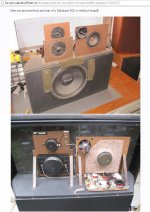
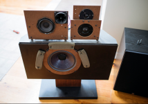
Everyone would think that it would have been easier for the manufacturer to place all those four drivers on a single piece of board. Then why did they choose to cut three boards instead?
Masochism combined with luck of diffraction knowledge?
I don’t think so. Most probably they tested various ways of drivers placement and they ended in there through listening tests.
I know someone who would like to test that journey to stratosphere scenario.

George
Attachments
Is that really you Derfy? The real one has hung out here long enought to know almost everyone here is an absolute expert. JC has been successful only due to dumb luck as so many here believe they know so much more.
Surely it's the same Derfy, remember, I went ahead and castigated JC only a week or so ago to punch my card! 😉
I don't get why the beligerence?
I simply stated that 1/4" roundover is purely a cosmetic thing, simple response to a shot from the hip comment.
Sharp edges cause diffraction from reflections as well. I should have said 1/2" as that's what I was actually thinking, 1/4" is too small.
The post, and others, you reference say it is a "negligible" , which is diminishing returns. They are only stating opinions on significance, where as they say there are differences in measurements however very slight.
Try it before you knock it. As much as you like the measurements don't get to decide the significance of the change subjectively.
The same reasoning, btw, would say that felt around the tweeter is useless. However it's well known it is one of the fastest ways to get rid of fatigue from HF.
Everyone would think that it would have been easier for the manufacturer to place all those four drivers on a single piece of board. Then why did they choose to cut three boards instead?
Masochism combined with luck of diffraction knowledge?
I don’t think so. Most probably they tested various ways of drivers placement and they ended in there through listening tests.
I know someone who would like to test that journey to stratosphere scenario.
George
That's easy. They cut the different boards for time alignment and baffle size relationship for desired frequency range SPL from each.
Everyone would think that it would have been easier for the manufacturer to place all those four drivers on a single piece of board. Then why did they choose to cut three boards instead?
It always baffled me how they converged on a design with so many variables. There must have been some initial technical decisions like time alignment or impulse response.
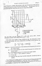
Nelson did not specify all the conditions, the only reference I found was for active noise cancellation under special conditions, mufflers, factory ducts, etc. They gave 500Hz at 140dB SPL distorts ~1% for every meter in a duct.
I pulled my number from the attached page, but if you scale your
140 dB to 100, then 1% becomes .01% and I think we're in the
ball park....
Attachments
Scott,
We started with an amplifier and in passing mention lack of symmetry is everywhere.
The extreme example was a compression driver. In normal use they really have been optimized. I don't do the usual. As a side note the actual thermal power handling and acoustic limits converge.
The cheap large systems require more than that. Quantity wise probably single digit sites. Worst case double digit. I am aware of a few such systems getting replaced fairly quickly.
BTY latest pro cone drivers at moderate power levels have less than 1% of each harmonic above a low frequency limit. Most current top of the line types show curves with less than 2% at 10% power levels. That is actual a bit above where I use them.
Last edited:
I pulled my number from the attached page, but if you scale your
140 dB to 100, then 1% becomes .01% and I think we're in the
ball park....
Good, now we have a conversation. Since a piston radiating into free space has zero distance confined in a pipe, x would be 0 in that reference. The answer is obviously somewhere in between. Is anyone here facile enough in the maths to give the right answer?
Good, now we have a conversation. Since a piston radiating into free space has zero distance confined in a pipe, x would be 0 in that reference. The answer is obviously somewhere in between. Is anyone here facile enough in the maths to give the right answer?
Not me. I presume it's lower as a function of wavelength.
That's easy. They cut the different boards for time alignment
The three baffles are displaced 5mm at most front to back from each other.
and baffle size relationship for desired frequency range SPL from each.
That maybe the case. SPL from vibrating panels (plus the SPL from diffraction).
i.e. voicing 🙂
George
Attachments
That maybe the case. SPL from vibrating panels (plus the SPL from diffraction).
i.e. voicing 🙂
Sounds like a non-convergent process. The first pic you showed looked like a re-cone on the woofer.
I find it amusing that simply pulling the fuse out of the piezo and connecting the ribbon without any modification of the crossover was considered a "big" improvement (the ribbon sat way above the rest).
(the ribbon sat way above the rest).
Well I have spent days and weeks trying to pick up differences playing with the 2x4 MiniDSP variable delay btn channels (drivers) on every reincarnation of my speakers setup.
No luck, I’ve given up (but I’m deaf).
George
No luck, I’ve given up (but I’m deaf).
George
No you are not, just an honest man.
I pulled my number from the attached page, but if you scale your
140 dB to 100, then 1% becomes .01% and I think we're in the
ball park....
Nelson,
That's pretty good.
Would you share the reference from which you pulled the page please?
- Not Audio Cyclopedia, 2nd ed.
- Not Radiotron Designer's Handbook, 4th ed.
- Not Reference Data for Radio Engineers, 4th ed.
- Not any Solid State Electrical Text, (at least that I can Identify).
- Not looking to be in the NEETs Series.- Not Loudspeakers by G.A. Briggs, 4th ed is only 88 pages.
Loudspeakers by G.A. Briggs, 5th ed @ 336pp ?
Cheers,
Last edited:
It always baffled me how they converged on a design with so many variables. There must have been some initial technical decisions like time alignment or impulse response.
It all starts with wavelengths. They control baffle step loss and how far the drivers can be seperated based on crossover points. If drivers are too far you get comb filtering. Sometimes you can swap polarity to help widen the gap, but you have to watch stuff like phase. From there you can consider lobbing patterns based on crossover type. Usually based on driver selection a designer will be able to imagine the crossover type so that'll be in mind when also designing baffles. Different crossovers can reduce or increase comb filtration. Some use eliptical hard crossover points so the drivers basically dont cross and can gain some distance that way.
- Status
- Not open for further replies.
- Home
- Member Areas
- The Lounge
- John Curl's Blowtorch preamplifier part III