But capacitor Dissipation Factor can't possibly make any difference at audio frequencies 😉.
You're making a cause/effect conclusion with no evidence. Isolating cause and effect is hard work and gets very boring and tedious when there is little additional reward. You're making sweeping generalizations after swapping out a component that has aged past its useful life.
Last edited:
I think you mean pre-distorting changing the zero crossover (time) would create lots of new frequencies.
Some numbers on SPL and non-linearity of air while listening to DQ-10's with a 10W amp might be useful.
As usual.... The reference was in compression drivers. Although they have enough diaphragm area it is the phase slots that reach pressure limits. As they typically have increased atmospheric loss with increasing frequency the maximum high frequency content is usually limited to 8,000 hertz. So not really worried about what comes out at 24,000 hertz.
As to listening level typical would be 60 ish dBa. So more than 30 dB of headroom. The loudest thing in the room otherwise would be my breathing.
Chris,
The old electrolytic's were still 10% high in value! However the equivalent series resistance was .12 ohms. This would result in the HF section increasing in output by -20 x log (8/8.12) or .13 dB assuming that was the original loss and the new capacitors have none. The inductance was not measurable. The major change would have been the reduction of the dissipation factor from .09 to .0001.
Based on my experience tuning and with golden ear others a level change of that size is not perceptible.
Last edited:
As usual.... The reference was in compression drivers.
As usual that was not the point, what signal processing on a complex music waveform achieves this continuous compression/rarefaction compensation? Second order pre-distortion is easy. Your fans don't listen to sine waves I assume.
As to listening level typical would be 60 ish dBa.
Mr. Marsh would be disappointed. I was hoping to do the same thing with my father's Magnepans but SY told me they are probably farkled and need new tweeter ribbons.
Last edited:
As usual that was not the point, what signal processing on a complex music waveform achieves this continuous compression/rarefaction compensation? Second order pre-distortion is easy. Your fans don't listen to sine waves I assume.
After the crossover in a large system the frequency range is from typically from 3,000 to 8,000 hertz. so although amplitude may vary it is not a complex waveform. Very easy to handle the process. Used to do it analog. Three op-amps and two diodes plus a few more passive parts.
Now done in the DSP unit.
As I understand it , it is the symmetry of the waveform around the zero crossing.I think you mean pre-distorting changing the zero crossover (time) would create lots of new frequencies.
(electrical part): The positive part and the negative part of the current waveform supplied by the amplifier.
(acoustical part): Then it’s the symmetry of the corresponding movement of a driver’s diaphragm depending on it’s construction and the sum of acoustic loading on either side of the diaphragm.
Some numbers on SPL and non-linearity of air while listening to DQ-10's with a 10W amp might be useful.
That would be interesting (freq sweeps for distortion vs SPL ).
I see different acoustic loading on each of the DQ-10's drivers. Closed box for the woofer, open baffle with back mechanical loading for the mid, sealed rear chamber for the two domes, front horn for the piezo.
Will the interesting (series/parallel) crossover has an effect on such electrically and acoustically generated distortion?
As usual....
I see I came a bit late. May the common love for the DQ-10s unite you
 🙂
🙂George
Attachments
Three op-amps and two diodes plus a few more passive parts.
Now done in the DSP unit.
Sorry my bad, I thought somehow this was related to the average in home listening experience.
That would be interesting (freq sweeps for distortion vs SPL ).
IME you will never be able to isolate driver non-linearity from the other effects. In a closed box at low frequencies you also have to take into account that the air is not isothermal either. IIRC total rarefaction is around 194dB so at 100dB SPL you are at 0.002% of the limit.
Advertising disguised as an informational piece with useful information, but it is just a sales tool.
He seems reasonably straightforward. I was lucky enough to meet Saul Marantz at CES
in Chicago during the 70s. David Hafler too.
Hi George,
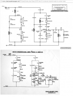
Thanks for the schematic of the crossover. I can't remember ever seeing it.
Hi Ray,
The white paper is more straightforward in part 1. In part 2 you get into the sales pitch for how they do things. I see he really doesn't like aluminium as a conductor, which almost electrolytic capacitors are made from. Then he gets into some of the more silly stuff used in audio sales for high end stuff.
-Chris
IME you will never be able to isolate driver non-linearity from the other effects. In a closed box at low frequencies you also have to take into account that the air is not isothermal either. IIRC total rarefaction is around 194dB so at 100dB SPL you are at 0.002% of the limit.
Almost. A 4" compression driver has a piston area around 7", the phase slots have an open area around .1" so the air rarefaction limit would be 157 dB at the phase plug!
At a typical efficiency on a 90 x 40 horn with an input of 1 watt the SPL at the phase plug would be 137 dB. So at 100 watts input we would expect distortion to occur. (And it does.)
To produce a concert level 102 dB average 112 dB peak at 100 feet would require 130 dB at the phase plug ignoring excess attenuation from high frequency air losses. Add in the 2 to 5 dB depending on humidity and you can see why modern professional compression drivers meet this need and no more.
So pretty much any application requiring more throw distance requires a bit more. Also rarefaction distortion is a soft growing distortion curve until you run out of air
Hello Ed,
The dissipation factor would come into play out of band for that filter section as long as it's of the same magnitude as the speakers and sound system. Also depends on ambient noise levels too. I would expect the mids and highs might sound smoother, more clear. The actual level difference wouldn't be something you would hear for those levels.
-Chris
Actually, what you measured is quite normal for old capacitors. These days you will have measured capacitance lower than the indicated value almost every brand of capacitor. Wouldn't it be nice if they used the marked value as a target so we would have a normal distribution around that figure.The old electrolytic's were still 10% high in value! However the equivalent series resistance was .12 ohms.
It depends on what frequency you are measuring the capacitors at as to whether you can see a level of inductance, just like when you measure the smaller capacitors.The inductance was not measurable. The major change would have been the reduction of the dissipation factor from .09 to .0001.
The dissipation factor would come into play out of band for that filter section as long as it's of the same magnitude as the speakers and sound system. Also depends on ambient noise levels too. I would expect the mids and highs might sound smoother, more clear. The actual level difference wouldn't be something you would hear for those levels.
Completely agree with you on this. But a change in timbre might be more audible to some of us. Probably not me at those levels. Age will do that to you.Based on my experience tuning and with golden ear others a level change of that size is not perceptible.
-Chris
Almost. A 4" compression driver has a piston area around 7", the phase slots have an open area around .1"
So this has what to do with George's suggestion re: the DQ-10 in a normal room? The shock wave from Krakatoa was estimated at 300dB and shock wave theory is needed to describe the behavior of many wind instruments, lightning even sparks.
Last edited:
So this has what to do with George's suggestion re: the DQ-10 in a normal room?
Agreed. It looked like Ed pulled a little slight of hand when talking about a small amp with a current source that was not up creating a symmetrical waveform at higher outputs. It was obvious from the first bit about compression vs rarefaction in speakers that it could only apply to compression drivers, although the little amp being discussed did not appear to be aimed specifically at that application.
So this has what to do with George's suggestion re: the DQ-10 in a normal room? The shock wave from Krakatoa was estimated at 300dB and shock wave theory is needed to describe the behavior of many wind instruments, lightning even sparks.
I take it you didn't read or comprehend my reply.
"It just points out that the assumption that a low distortion drive will not guarantee low distortion output may not hold. Over the years a number of folks have used asymmetric drive to do everything from lower costs to reduce distortion. In high power systems using compression drivers you have a rarefaction limit but not a compression one. So deliberately lengthening the rarefaction time and decreasing the compression time allows safer or greater output. The HF distortion that results is often well above any frequencies that are perceptible and also greatly attenuated by air loses."
ISome numbers on SPL and non-linearity of air while listening to DQ-10's with a 10W amp might be useful.
Thumbnail calculation, I get somewhat less than .01% 2nd.
I get somewhat less than .01% 2nd.
Nice if there were (normal cone) drivers that did that. Mr. Marsh must have a hard time getting the ppm's of amp performance cranking those M2's.
Last edited:
Don't get your drift here, they imaged an over the air broadcast by Victor Campos like nothing I ever heard before or since. This was FM radio through 80's electronics. Around this time a $50k Thiel/Cello setup drove me out of the room.
My anecdotal subjective experiences from distant memory are as valid as anyone else's. The great pile of metadata.
I didn't say they were bad... It's just clear they're bleeding diffraction everywhere. It wouldn't be hard to just cut some boards 1/4" larger than the existing ones on the correct edges, then give them 1/4" round overs. In a few places you might have to stick some absorbing material. Doing that might take them into the stratosphere.
Destroyer,
1/4" isn't going to change a thing in comparison to the tweeter's directivity itself:
Baffle diffraction and roundover radius? -
Techtalk Speaker Building, Audio, Video Discussion Forum
1/4" isn't going to change a thing in comparison to the tweeter's directivity itself:
Baffle diffraction and roundover radius? -
Techtalk Speaker Building, Audio, Video Discussion Forum
I didn't say they were bad... It's just clear they're bleeding diffraction everywhere.
Fair enough, I had the add on ribbon tweeter with plenty of sharp edges. I had friends who loved to slop bituminous felt everywhere with inconclusive results.
- Status
- Not open for further replies.
- Home
- Member Areas
- The Lounge
- John Curl's Blowtorch preamplifier part III