On a more positive note, I do remember Michael Gerzon fondly. I first met him in 1975 at an AES (London) convention, and I was invited to Oxford to hear his sound system through Peter Craven. He really knew his stuff! And the sound, fascinating. He showed that more processing makes for worse sound quality. Dolby was one of the problems. He had examples of old 78 records that in most ways sounded wonderful. Many people have been fooled by Dolby over the decades. I got both Michael and Richard Heyser together at another AES, in order that they would know each other better. These two DID KNOW what was happening in audio reproduction. I miss them both.
Last edited:
In other words, you can't be bothered? Here you are then, one of the references from the link above https://pdfs.semanticscholar.org/2e6b/5b6ec83e229c1ab06108f731582de7368298.pdfOn a more positive note, I do remember Michael Gerzon fondly.
The Rod Elliott article I linked to is worth reading, none of this stuff is new and there are pros and cons like everything else
Excuse me please, Earl Geddes, I know he does not subscribe to BS but he knows more than you about loudspeakers.There are no loudspeaker experts here, to my knowledge.
Let's see..... what conditions are met that produces the most back/counter EMF from a coil/magnet (speaker)?
Fast, high amplitude excursions of coil past magnet field. Where does that happen? At resonance. Resonance... where the efficiency is highest; Low input give max excursion output.
High Q resonance will produce more than a low Q.
Thus, parallel R will kill Q and reduce back EMF.
??
THx-RNMarsh
Fast, high amplitude excursions of coil past magnet field. Where does that happen? At resonance. Resonance... where the efficiency is highest; Low input give max excursion output.
High Q resonance will produce more than a low Q.
Thus, parallel R will kill Q and reduce back EMF.
??
THx-RNMarsh
Last edited:
Geddes might be helpful, but he is not contributing to this thread, unless one of you is hiding behind an alias, and is really him. '-) I am not a loudspeaker expert, but I know when people actually do know more about them than me, and that does not include any of you guys.
perfect voltage amplifier is already shunting with zero ohm impedance, how can additional shunt resistance do anything?
Geddes might be helpful, but he is not contributing to this thread, unless one of you is hiding behind an alias, and is really him.
True, he would dismiss all of this as a waste of his time.
But Richard has "invented" mixed mode amplifier and it trying to work out the pros and cons 😉perfect voltage amplifier is already shunting with zero ohm impedance, how can additional shunt resistance do anything?
Dutch & Dutch 8c active loudspeaker system Measurements | Stereophile.com
It's a lot of money at $12.5k a pair but seems to be preferred to the Kii3 by some. Of course as per the Kii will be hated by audiophiles as takes a digital input and then gets on with it. No tweaking or synergistic amp swaps. Just lovely accurate music.
I heard them and actually spoke to Maarten at NWA.
He came to listen to the Graham LF9/f's we were demo'ing with our gear and told me he was very impressed with the sound and I took a listen at theirs.
I think with the D & D you need a good source - I do not think the stuff they partnered with (per the local dealer in the UK) did the speakers any favours which is a pity because I've been told they can really sing in the right set-up (source was a very amateurish looking tube pre with digital streaming/HD) source). They are beautifully made BTW.
I would agree that this is all a waste of time. You guys pontificate like 'Sophomores' (look it up in the dictionary) about subjects that you know little or virtually nothing about. I would like to talk about electronics modifications again. This is where the tread first started and should continue. Richard is trying, and Dan and Joe have some interesting ideas, but enough is enough, don't you think?
Actually, you've set the bar pretty low there dude..😀I am not a loudspeaker expert, but I know when people actually do know more about them than me, and that does not include any of you guys.
The real issue with loudspeakers is they are a complex mix of acoustics, mechanical engineering, and electrical engineering.
From my expertise, I can see where these experts fall short in their understandings. But I can only critique them when it is within my domain.
jn
here in lies the assumption that causes the problem and why one cant figure out how the R works. Look at the buffering of the series Z of the interconnect between the amp and loudspeaker. If you connect - lets make it exaggerated - 20 foot pile of #18 zip cord to a dynamic speaker while you attempt to measure the THD ---- While the test is made at the amps output terminals, you get a steady number. At the other end... at the speaker terminals you get higher and erratic numbers. ... the effect of the back EMF at play. The worst case is at low freqs (around resonance of the speaker system). If you listen near field and with very short amp leads to speaker, all is close to your perfect/Ideal condition. Same results at either point tested. The "short" is only at the speaker terminals of the amp. The greater the series Z between dynamic driver and amp, the greater the parasitic effects. You really do need low series R as well as low series Ls in a speaker cable.perfect voltage amplifier is already shunting with zero ohm impedance, how can additional shunt resistance do anything?
THx-RNMarsh
Last edited:
I would agree that this is all a waste of time. You guys pontificate like 'Sophomores' (look it up in the dictionary) about subjects that you know little or virtually nothing about.
Which is why I primarily discuss aspects where I am indeed a high level expert, and ask questions on aspects I know little of.
And you pontificate like a sophomore on how much more knowledgeable you are than any of us on whatever the topic dejour is.
Indeed Richard is...And I elaborated at length on how his layout might have played some role in his results. I must say, I guess I somehow missed your highly technical elaborate posts discussing his results and what caused it...I would like to talk about electronics modifications again. This is where the tread first started and should continue. Richard is trying
Well? Or are you just going to post about others being un-knowledgeable?
jn
here in lies the assumption that causes the problem and why one cant figure out how the R works.
Look at the buffering of the series Z of the interconnect between the amp and loudspeaker.
If you connect - lets make it exaggerated - 20 feet of #18 zip cord to a dynamic speaker while you attempt to measure the THD ----
While the test is made at the amps output terminals, you get a steady number. At the other end... at the speaker terminals you get much higher and erratic numbers. ... the effect of the back EMF at play.
The worst case is at low freqs (around resonance of the speaker system).
If you listen near field and with very short amp leads to speaker, all is close to your perfect/Ideal condition. Same results at either point tested.
THx-RNMarsh
Do you have test results that correlate to that? THD at each end of an 18 zip?
I honestly think that Ed would be more interested it this effect as he runs rather long speaker cables, a thousand feet more or less.. I wonder if he has any plots..
jn
Speaker cables don't influence harmonic distortion!Do you have test results that correlate to that? THD at each end of an 18 zip?
Ed was insulted the last time he contributed measurements (on resistors, as I remember), but he would be the best person to ask.
Richard, I have not followed your topic here with this added resistor, but it seems to me that many cables are also helped by termination with a Zobel network R+C, or just an R (if it can handle enough power and approximates the cable characteristic impedance. It would seem to me that too low a value of R, would not match the cable, but would also load the amp significantly. What are we talking about here?
Richard, I have not followed your topic here with this added resistor, but it seems to me that many cables are also helped by termination with a Zobel network R+C, or just an R (if it can handle enough power and approximates the cable characteristic impedance. It would seem to me that too low a value of R, would not match the cable, but would also load the amp significantly. What are we talking about here?
Look, this is simply not true!! I will make one and last attempt to explain and stay polite.At resonance. Resonance... where the efficiency is highest; Low input give max excursion output.
High Q resonance will produce more than a low Q.
Thus, parallel R will kill Q and reduce back EMF.
??
THx-RNMarsh
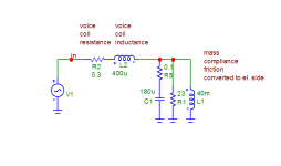
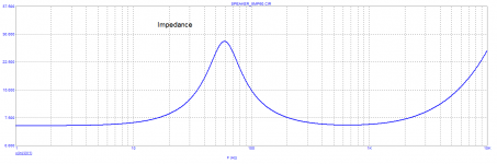
Attached is an electrical equivalent speaker circuit. It is simplified, but valid for explanation. R2 and L2 are voice coil resistance and inductance. However, they do not make the resonance!!. Resonance is mechanical and is created by mass and compliance, this transfers to electric diagram as L1 and C1. This C1 and L1 make the resonance, damped by R1 and R2+L2. Now, you want to add a damping resistor to point IN, across V1. What do you get? Nothing! You may short IN to GND but R2 voice coil resistance and L2 voice coil inductance still remains. Moreover, IN is already shunted by V1. You have no access to damp the R1//C1//L1 resonance.
Attachments
- Status
- Not open for further replies.
- Home
- Member Areas
- The Lounge
- John Curl's Blowtorch preamplifier part III