In the case of OPS transistor failure (shorted power devices), there is no control of the DC thru them to the speaker. Only a series relay to disconnect the current from speaker to prevent speaker damage.
Other use is to prevent the turn-on transient from making annoying 'pop' or 'bang' sound from speakers.... so most use the relay in delay mode until dc has stabilized and zero offset on speaker terminal before relay closes.
-RM
In case of OPS transistor failure the power regulator will switch off the power much faster then relay will disconnect output. The DC control is separate part detection, nothing to do with OPS transistors.
Switching off mains supply is not good solution, big power supply capacitors still have enough charge to damage loudspeaker. My regulator is connected after big power supply caps, only much smaller caps situated on the amp board will discharge via loudspeaker, and this is not danger for woofer but could be to twitter. Normally in passive crossovers twitter is connected via a capacitor. In case of active crossovers I always connect twitter via additional capacitor.
BR Damir
Last edited:
It is not only about reliability, about works/fails. It is about continuous degradation of the relay contact surface during long-term operation and interrupting current, leading to non/linear contact resistance and increased distortion. This is certainly not an issue in cars, but is an issue in linear audio. Please do your own tests on power speaker relays before making conclusions.
I believe you. I have only been referring to why relays are used at all for protection. There are relays which do not deteriorate at the contact point. Maybe not used in audio amps, though.
One of my Go-To books on contacts is the early work by Ragnar Holm. "Electric Contacts" 1981 4th edition Another from my library is "Switch Engineering handbook" John R. Mason. 1993.
Hard gold over silver over copper with wiping action of contacts upon open and close and of contactor construction can be very good for a high number of cycles.
However, as suggested it might be good to replace any relay or contactor in the event of OPS failure which can exceed the contacts normal rating.
Though I have not seen it used on speaker relays -- only power switches -- an RC across the contacts will minimize arc burn/pitting.... a real concern for creating poor contact performance over time.
The peak discharge current of even caps in bypass right at the OPS devices can produce very high current peaks..... beyond any tweeter can usually handle..... limited only by the esr of the cap and pcb trace. But less to the speaker due to cable/interconnect Rs. but still.... PS voltage dumped into a fraction of an Ohm is still a lot of current even if the period is short. The speed at which a dynamic tweeter VC can act as a fuse is amazingly fast.
THx-RNMarsh
Last edited:
Hi Richard,
I've made it a point to replace the relay with output failures. It is pretty much a certainty that the contacts will be burned or badly pitted as a result of the failure. Marantz receivers were capable of melting the contacts together. Seen that more than once.
I have seen permanent magnets glued or taped to the sides of some relays in an effort to blow out the arc. I'm not sure how effective that is, but when replacing those I'll move the old cover to the new relay to retain that feature.
-Chris
20 hertz sine wave passed through the higher DA capacitor compared to a better one built intp the AP unit.
Hi Simon, what is the input voltage and the load value? Did you pull "higher DA capacitor" from your trash can/barn?
Normally in passive crossovers twitter is connected via a capacitor. In case of active crossovers I always connect twitter via additional capacitor.
BR Damir
Totally not making fun of you in the least (I admire your clarity in what is not your native tongue!) but "twitter" versus tweeter amused me. 🙂
And, yes, I'm also doing active but made one of the poles a series capacitor for insurance as well.
Why do I need a relay for my speakers when there is a perfectly good 200 amp breaker in my panel.
Hi Simon, what is the input voltage and the load value? Did you pull "higher DA capacitor" from your trash can/barn?
2.2 uF into 10K 1 VRMS. Just picked the physically smallest one from the 2.2 uF bin in my capacitor drawer. If I get around to it I can run a few more samples. But I did want one that was far from perfect. I did run a capacitor sold for audio use and it was much better but still showed the results expected.
I finally had time to post some pretty pictures.
First is the classic step function. Not quite perfect but close enough. This is essentially the signal you get when you close a switch to a power supply.
Next is the output across a 10,000 ohm resistor when the step function is passed through a capacitor with 5% "D" according to my bridge. Some folks seem to confuse this with linear algebra's definition of linearity, but clearly the graph is not a straight line.
Third is a classic 20 hertz square wave image (Not perfect) and the square wave passed through the capacitor of 2.2 uF. Note that due to phase shift the apparent amplitude has increased by what looks like enough the perception may be the tone is louder. This is due to the phase shift that may also present itself in addition to the increase in amplitude.
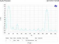
Fourth is an FFT of the 20 hertz sine wave passed through the higher DA capacitor compared to a better one built intp the AP unit. A quite dramatic increase in the harmonic distortion.
Finally is the IM distortion caused in both the good capacitor and the high DA one. Note there are always side bands due to the heterodyne caused by the nonlinear capacitor VI curve. Much worse with the high DA capacitor.
Naturally the curves are real as demonstrated by the 60 hertz incursions.
Yes. And what is the dielectric for the cap under test that gives D=5% ? Replacing several of those in a system will make a noticable difference in sound quality.
THx-RNMarsh
RNM,
Not really sure, unmarked except for value. As I have learned from measurements over the years even with the same dielectric higher voltage film parts work better due to less dc/dt.
Don't have any beeswax capacitors for humorous comparisons.
Not really sure, unmarked except for value. As I have learned from measurements over the years even with the same dielectric higher voltage film parts work better due to less dc/dt.
Don't have any beeswax capacitors for humorous comparisons.
Aren't those gold over silver over copper relays small signal relays for analog switching, not for speaker switching where there are potentially large currents involved.
Similar to the AXICOM IM07 series.
Similar to the AXICOM IM07 series.
RNM,
Not really sure, unmarked except for value. As I have learned from measurements over the years even with the same dielectric higher voltage film parts work better due to less dc/dt.
.
Very true. Higher voltage caps measure better in almost every parameter. This is especially true for polar and bipolar electrolytic type. Also, 105C rated caps are much better than 85C caps.
I always use 105C rated when electro types are needed. They also generally have longer life.
THx-RNMarsh
Last edited:
Totally not making fun of you in the least (I admire your clarity in what is not your native tongue!) but "twitter" versus tweeter amused me. 🙂
And, yes, I'm also doing active but made one of the poles a series capacitor for insurance as well.
Yes that's funny, my bad.😱
And, yes, I'm also doing active but made one of the poles a series capacitor for insurance as well.
A new kind of insurance? 😉😀
Aren't those gold over silver over copper relays small signal relays for analog switching, not for speaker switching where there are potentially large currents involved.
Similar to the AXICOM IM07 series.
What relays are you referring to?
A new kind of insurance? 😉😀
Solely depends on capitalization. 😉 The chap I found keeps a close eye on my volume control for sure, haha.
More fun. A 1.8 uF 160 VAC 250VDC Bennic brand metalized polypropylene capacitor into a 10,000 ohm 1% metal film 1/4 watt resistor. 5 volts RMS at 20 hertz and .5 volts RMS at 200 hertz. DC coupling out of the AP. Nicely shows the harmonic and intermodulation distortion. I will run the test again tomorrow to be sure it holds up.
Attachments
Last edited:
More fun. Nicely shows the harmonic and intermodulation distortion. I will run the test again tomorrow to be sure it holds up.
Nicely, really? Since the 60Hz can't be differentiated from hum no claims to its origin can be made and since 20 and 200 are exactly divisible there is no definitive proof of IM here either. You do love confounders don't you? Besides if the 60Hz is hum everything is -115dB or better not exciting.
EDIT - That's an 8.8Hz corner so there is considerable AC voltage on the cap and the fundamental magnitude is off on the plot.
Last edited:
The relay coil produced magnetic field is intimately close to the relay switch conductors and contacts.
What is the effect of relay coil stray magnetic field on signals passing through a typical relay ?.
Ditto permanent magnets in relays (bistable relays).
Dan.
What is the effect of relay coil stray magnetic field on signals passing through a typical relay ?.
Ditto permanent magnets in relays (bistable relays).
Dan.
Last edited:
Linear audio 13 looked at that. Mainly focussed on reed relays, but measured std ones as well. The std ones were waay down in the weeds. This was looking at small signal work not power amp outputs, but at power amp levels the effects will be even less.
- Status
- Not open for further replies.
- Home
- Member Areas
- The Lounge
- John Curl's Blowtorch preamplifier part II