John,
Thank you for sharing.
We have looked at the 2SK2381/2SJ407 pair some time last year, for potential use in headphone amp output.
They have ~3x higher Yfs but also higher capacitances than 2SK2013/2J313.
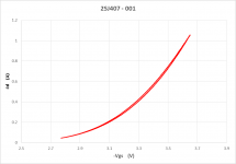
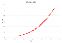
So we were curve tracing them on a 40°C heater block, driving them between 0A and 1A using a 100Hz triangular wave. Vds was 15V.
Our DUTs showed thermal hysteresis clearly visible on our curve tracer.
By that I mean the DUTs followed a different curve when current was increasing to that when current was decreasing during continuous mode.
The cause is most likely a very high tempco.
No such phenomenon is visible for 2SK2013/2SJ313.
Perhaps you are using them with much lower dissipation ?
Best regards,
Patrick
.
Thank you for sharing.
We have looked at the 2SK2381/2SJ407 pair some time last year, for potential use in headphone amp output.
They have ~3x higher Yfs but also higher capacitances than 2SK2013/2J313.
So we were curve tracing them on a 40°C heater block, driving them between 0A and 1A using a 100Hz triangular wave. Vds was 15V.
Our DUTs showed thermal hysteresis clearly visible on our curve tracer.
By that I mean the DUTs followed a different curve when current was increasing to that when current was decreasing during continuous mode.
The cause is most likely a very high tempco.
No such phenomenon is visible for 2SK2013/2SJ313.
Perhaps you are using them with much lower dissipation ?
Best regards,
Patrick
.
Attachments
Last edited:
1% duty cycle pulse testing will reduce the measurement uncertainty by a factor of 100X. But it's more difficult to do than applying a triangle wave.
We can do anything, including pulse testing.
But pulse testing does not represent actual operating conditions.
And we know for sure what is shown is actual measurement result.
And not measurement uncertainty.
Whether you still see the same hysteresis under a much lower bias or dissipation, or a dynamic range, is another matter.
It may not matter in John's application.
But we have (IMHO) better devices to choose from where we do not see this under the same test conditions.
Cheers,
Patrick
Last edited:
Just to illustrate the differences.
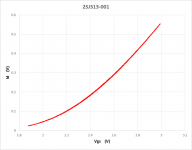
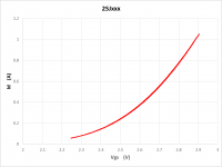
Here are two more measurement results using exactly the same equipment and test conditions.
The only exception being that a lower current range was used for the well-known 2SJ313.
The unnamed device (not known or used in audio) is quite comparable to the 2SJ407.
It is also a switching FET by a Japanese semiconductor manufacturer which no longer exists.
i.e. if they can still be found, they are either NOS or fake.
Hence unnamed.
Patrick
.
Attachments
Hi John,
Very interesting using a mosfet to drive the output stage and reduce load on the Vas section. Revox did this with the B242 amplifier.
-Chris
Very interesting using a mosfet to drive the output stage and reduce load on the Vas section. Revox did this with the B242 amplifier.
-Chris
Don't it add a pole ? Better to use directly Mosfets AS output devices, don't you think ? With some other benefits, like protection against secondary breakdown and no need for thermal compensation.Hi John,
Very interesting using a mosfet to drive the output stage and reduce load on the Vas section.
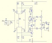
The front-end of John's Parasound A23 (up to the driver MOSFETs) has been reincarnated as a headphone amplifier.
It is widely known in China, but also through some eby dealers, as the WeiLiang E4 HPA.
Full detail can be seen here (just use google translate) :
E4 ???FET?????MOS?????????718?????-???
Apart from some simplifications (cascode, etc. necessary for the high rail voltages in the A23), the circuit is pretty much a 1:1 copy.
The output stage has of course much higher bias (60mA standard, 150mA recommended) and much lower source resistors.
Because they also eventually ran out of 2SK170/2SJ74 pairs, it is now being supplied with 2SK246/2SJ103 biased at ~2mA.
Apparently very popular in China and >> 5000 examples have been sold.
Patrick
.
Attachments

Hi EUVL, you have done your 'homework' and I respect your findings. Yes, the Tempco differences between the lateral mosfets and the other devices could show a hysteresis as you have shown. In our case, because the driver is not loading much, its dynamic temp does not change much, BUT you made an important point, even a discovery.
As far as the Chinese are concerned, they are mainly copying the original Levinson JC-2 line stage and adding a complementary mosfet output stage to it. We also did that in the mid 70's for the Levinson LNC-2 (I think that was the designation) active Xover modules.
As far as an extra pole is concerned, usually we have a bipolar pair in place of the complementary mosfets, or a Darlington output stage, and the mosfet drivers are usually superior, but you are right that direct driven mosfets for the output stage would be simpler. The problem with instability is not too significant in this situation as we are working with followers only.
Last edited:
John,
It was not meant to be a criticism.
I just wanted to point out why MOSFETs designed for switching are not always suitable for linear applications.
Even when they come from respected manufacturers like Toshiba.
There are of course exceptions, as illustrated by the "unnamed" device.
Regards,
Patrick
It was not meant to be a criticism.
I just wanted to point out why MOSFETs designed for switching are not always suitable for linear applications.
Even when they come from respected manufacturers like Toshiba.
There are of course exceptions, as illustrated by the "unnamed" device.
Regards,
Patrick
I see the problem, but I don't know its relative importance with typical circuits. We have tried both types as drivers in my more recent designs, and each had problems. Actually, we usually use what is most easily available under these conditions, if we can't demonstrate a real difference in performance. However, Charles Hansen thought also that the lateral mosfets were really better for his circuits. I always have the problem of the low Gm with these devices.
Striking resemblance to what Charles Hansen found when he put IR P channel on curve tracer he described here, some 85k posts ago in this very thread here, he also mentioned that a Siemens engineer explained the problem as process related.... hysteresis clearly visible on our curve tracer.
By that I mean the DUTs followed a different curve when current was increasing to that when current was decreasing during continuous mode.
The cause is most likely a very high tempco. ...
John,
TO220 laterals are non existent on the market.
Maybe people have private stocks here and there, but no good for new products.
Suggest you try Fairchild FQP3N30 / FQP3P20.
Tips from Nelson.
Patrick
TO220 laterals are non existent on the market.
Maybe people have private stocks here and there, but no good for new products.
Suggest you try Fairchild FQP3N30 / FQP3P20.
Tips from Nelson.
Patrick
I tried some quick simulation of the A23 circuit as in the pdf.
Seems to be using quite an amount of Negative Feedback.
Am I correct ?
Patrick
Seems to be using quite an amount of Negative Feedback.
Am I correct ?
Patrick
I have no idea. They have them listed.
That's up to Parasound to inquire if they are interested.
Pacific Semiconductor claims:
189 ea. 2sj79 @ $5.77
120 ea. 2sk216 @ $5.25
That's up to Parasound to inquire if they are interested.
Pacific Semiconductor claims:
189 ea. 2sj79 @ $5.77
120 ea. 2sk216 @ $5.25
Last edited:
Of course I use a lot of negative feedback, EUVL. I have to make specs with a class AB-2 design. You might be able to better with a lot of extra work, but we have to be practical with Parasound designs.
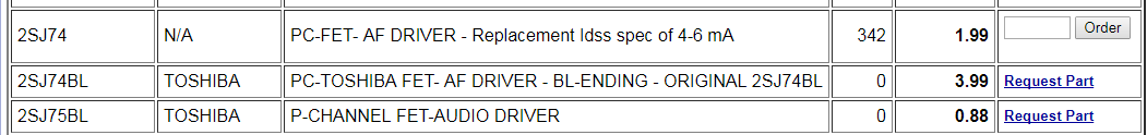
2SJ74 Toshiba,TO-92 | IC Chips | UTSOURCEYeh.
They also claim to have 342 pcs of 2SJ74's at 2 USD each.
Bargain of the decade ??
Patrick
- Status
- Not open for further replies.
- Home
- Member Areas
- The Lounge
- John Curl's Blowtorch preamplifier part II