Some people are easy. I would have held out for a 7704 if my chronology is right. Where I started we had a brace of 547s and 1 7704 with the pushbutton attenuator plugins. The 7704 was like something from the far future.
In 1964? 😎
Jan
I have the same problem with an amplifier that has lots of parallel common source
input FETs, so the capacitance plays a big role. Most of Cgs is removed by the
feedback into the source and Cgd is removed by bootstrapping the drain via the
cascode transistors. Gate, source and drain move more or less unison, voltage-wise,
which is kinda weird. It works for small signals, but I cannot dim down the 4274A
bridge to a level that does not kill the proper feedback during capacitance measurement.
It seems I can circumvent that by using the vector network analyzer, using 1 Hz
bandwidth and attenuating the level during S11 measurement to -50 dBm or so.
The VNA starts at 300 KHz only, with uncalibrated under range to 150 KHz.
But S-parameters love 50 Ohms and are not really precise in a hi-resistance
environment.
Looks like I need an impedance analyzer.

\Gerhard
This is something I haven't mastered yet, although I do have a Bode 100.
Jan
what makes for a good audio design?
good parts
good layout
good circuit design
good power supply
good heatsinking
good chassis design & module placement
Some of the above just possibly might require painstaking trial and error, to discover which of N experimental test units, has the greatest amount of audio goodness. Passive parts vendor selection perhaps. Some people might be tempted to say that hand-matching transistor pairs is an example of painstaking trial and error.
_
Now define the rules for "good".
Good luck.
You are right. The 7704 is from 1969. In 1964 the "flagship" was the 547.In 1964? 😎
Jan
Measuring capacitance in active circuits is a hairy subject when your nodes aren't referred to ground (or common, however you want to define that). The only thing I can think of would be to add different values of known capacitance and measure circuit changes, then figure out what the existing capacitance is. I can't think of any other method that doesn't completely disrupt the circuit.
-Chris
-Chris
Hi Demian,
Some instruments are simply classics that don't have exact equivalents today. I know I can get 'scope probes that do the clamp-on thing, but they aren't (well, weren't) that accurate as the 428 was. I guess if I had north of $20K to drop on a new scope, then the special probes, I might not think this way. But most of us don't and we make due with what we can put together. I really like using the 428, and I'll admit it!
Thanks for bringing that instrument up Demian, I'll look it up. But after the RTX, my instrument buying days are behind me for a while. BTW, I really like the RTX so far. Thanks for your involvement and comments for that equipment.
-Chris
That goes for a lot of my instruments. I still love using the HP 428B DC clamp on ammeters. This instrument is a tube based unit that was still manufactured up into the 80's. That sounds pretty recent to me until I do the math, that was 30+ years ago!Tel made a special instrument for that task. The 130. There is nothing else like it and its long obsolete.
Some instruments are simply classics that don't have exact equivalents today. I know I can get 'scope probes that do the clamp-on thing, but they aren't (well, weren't) that accurate as the 428 was. I guess if I had north of $20K to drop on a new scope, then the special probes, I might not think this way. But most of us don't and we make due with what we can put together. I really like using the 428, and I'll admit it!
Thanks for bringing that instrument up Demian, I'll look it up. But after the RTX, my instrument buying days are behind me for a while. BTW, I really like the RTX so far. Thanks for your involvement and comments for that equipment.
-Chris
For input C the old Tek cal method also works. Take a suitable HF signal 10 KHz for example and measure the change in input level with a series resistance. With compensation for the input R its just arithmetic. However less useful for internal nodes etc. Tek had a box for this. Its necessary for consistent probe compensation.
I have 2 130s I got years ago. They were cheap then.
There is a solid state version of the 428 by the guy who created it. And someone posted a circuit to work with the probes on DIY. It was quite the undertaking. The bandwidth is quite limited however. (I have two of the electronics here somewhere.)
Hi Demian,
A solid state version of the 428B sounds interesting. I don't have any issues with the tube models, but solid state would be lighter and cooler. I think the probe is the limiting factor in AC response. It was designed for measuring DC after all. By using the monitor out jack, you will have AC response to about 200 Hz. That would cover 60 Hz and up to the 3rd harmonic. But then you should be reaching for the AC current probe if you are looking for AC frequency response. I think the meter portion of the 428 only indicates the DC measured current.
The amazing thing about this instrument is that the lowest scale is 1 mA FS! Not too shabby for a clamp meter. It tops out at 10 amperes. For me, that means that something just ceased to exist and is now just a wire disguised as a component of some sort.
I'll search for that thread Demian. A big thank you to your memory! 🙂
-Chris
I just don't understand all this 42 crap at all.
But, I will state it here for all to hear, when I go traveling about, I bring my own towel.
Any questions?
But, I will state it here for all to hear, when I go traveling about, I bring my own towel.
Any questions?
The 428B is very useful
I find my TEK P6042 to be a solid state equal or better.
Good specs.
THx-RNMarsh
I find my TEK P6042 to be a solid state equal or better.
Good specs.
THx-RNMarsh
Last edited:
I got one of these.... When I called the calibration guy, he told me the newer stuff is magnatudes more accurate.
Hemmm, so how does that 130 work? You send the 100kHz signal through the DUT and measure the caps along the way?
Do your's still work?
Would I be better off taking you up on your offer for borrowing the plug in units?
Cheers
Hemmm, so how does that 130 work? You send the 100kHz signal through the DUT and measure the caps along the way?
Do your's still work?
Would I be better off taking you up on your offer for borrowing the plug in units?
Cheers
Attachments
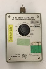
The Tek 130 resonates the test cap with an internal oscillator and the frequency shift is proportional to the capacitance. The delta standard is for checking or calibrating the 130. I believe the manual is online. Like all Tek (and HP) manuals of the period you can learn a lot from reading it.Richard,
Is that the probe for the 428B?
Nice cowboy hat by the way.
Cheers,
Richard,
Is that the probe for the 428B?
Nice cowboy hat by the way.
Cheers,
No, it's the full instrument model number.
The hat? Thx. Its something from ... The Double S. Sancho. I have a collection of hats.
-Richard
The 428B is very useful
I find my TEK P6042 to be a solid state equal or better.
Good specs. DC- 50MHz
THx-RNMarsh
Many years ago I was able to getb a Tek TCP312 current probe with its TCPA300 preamp. This probe has a very ingenius combination of a split-core clamp-on for AC and a Hall effect sensor so it starts at DC.
The only combination I know which lets me measure down to 1mA with acceptable S/N.
Jan
The only combination I know which lets me measure down to 1mA with acceptable S/N.
Jan
I got one of these.... When I called the calibration guy, he told me the newer stuff is magnatudes more accurate.
Hemmm, so how does that 130 work? You send the 100kHz signal through the DUT and measure the caps along the way?
Do your's still work?
Would I be better off taking you up on your offer for borrowing the plug in units?
Cheers
The 130 has two oscillators. If you null it you make the freq equal. Then one is connected to the circuit under test which will change it's frequency. They measure the delta in freq and that is a measure of the external capacitance.
Jan
Pretty bad even on axis, and when bad on axis, then there is NO cure. This is very interesting, that so many so called high-end speakers are so so bad. The only advantage usually is that you can play them at high volume level.
I know a large loudspeaker company that bought these speakers to understand the competition better, because they got rave reviews, but on the face of it seemed to contain some incomprehensible design decisions. They found out that they did. Even on axis, as you say, the darned things aren't very straight. But they are euphonic. That sells.
Back EMF does not occur in a properly designed and aligned speaker system. However, as we have discussed in this thread, not all speaker systems are perfect. In that case, any back EMF produced will be absorbed by the output impedance of the amplifier. IOW: It is a non-problem in a properly designed speaker and/or when using a properly designed amplifier.
Of course, if one is using an improperly designed speaker system and a poorly designed amplifier....
Back EMF will increase impedance so what is so wrong with that? And it is always there when a voice coil moves through a magnetic field, which is what happens when you hear sound coming from your speakers.
Last edited:
- Status
- Not open for further replies.
- Home
- Member Areas
- The Lounge
- John Curl's Blowtorch preamplifier part II