Where have I seen this before...
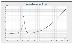
I mentioned before about designing a loudspeaker cable. Attached is the impedance graph of a real loudspeaker. (Single driver not a complete system.)
Simple questions, what causes the low frequency spike, what causes the gradual increase in impedance and bonus question what causes the discontinuities?
Super bonus question what normally would be the rated impedance of this driver?
Attachments
Last edited:
I mentioned before about designing a loudspeaker cable. Attached is the impedance graph of a real loudspeaker. (Single driver not a complete system.)
Simple questions, what causes the low frequency spike, what causes the gradual increase in impedance and bonus question what causes the discontinuities?
Super bonus question what normally would be the rated impedance of this driver?
20 questions again? This stuff is tediously covered in literally hundreds of DIY oriented articles by now.
20 questions again? This stuff is tediously covered in literally hundreds of DIY oriented articles by now.
Really? Then let me know what the rated impedance of this driver could be?
But the first question is the really interesting one.
.Really? Then let me know what the rated impedance of this driver could be?
But the first question is the really interesting one.
Go ahead and answer the questions and see what folks have to say if anything. It's known as Google/Images "speaker in a box impedance" dozens of links with essentially the same image.
I won't play anymore.
The discontinuities at 10, 100, 1k, 10KHz are probably an off-by-one error
in your software at the decade boundaries.
in your software at the decade boundaries.
I struggled for nearly a year trying to optimize a charge preamp based on a spurious shot-noise theory for JFET noise put forth by a pair of Princeton astronomers, which led to a wrong expression for a figure-of-merit. I also have a chatty book about transistors which attributed JFET noise to shot noise (Feldman, The Physics and Circuit Properties of Transistors, from 1972). Finally I discovered that the nuclear science people knew what they were doing, and they as well referenced various Van der Ziel papers. Finally I was on the right track.EDIT - OK I read it. To be fair even Felix A. Levinzon once said JFET's have shot noise in one of his tutorial articles. The noise figures carried out to 3 places are silly considering that the .667*gm number comes from a guess at the junction grading (which as I measured the BF862 beats). There a a few articles by Van der Ziel where the editors struggled to figure out a way to fit his exact noise equations on the page.
It is scary how much misinformation is out there. John Linsley Hood mentioned that charge "tunneled" through the pinched-off biased channel, and Whitlock upbraided me for criticizing this language. One must not criticize the masters.
The discontinuities at 10, 100, 1k, 10KHz are probably an off-by-one error
in your software at the decade boundaries.
That seems to be exactly it. If they were not at switching boundaries such as the one just below 5K they would normally be caused by either external noise during the sweep or if repeatable then a rip, tear or rub. (BTY not my measurement just pulled a nice example.)
Scott,
No one asked you to play. But the answer to rated impedance would be anything from 7 ohms to 14 ohms for 20-20K. The maximum RATED impedance (AES) is twice the minimum.
And yet you started another round of tedious 20 questions by quoting Scott.Scott,
No one asked you to play.
If you did not intend to "ask him to play", then you shouldn't have quoted him.
Seems simple, no?
John
And yet you started another round of tedious 20 questions by quoting Scott.
If you did not intend to "ask him to play", then you shouldn't have quoted him.
Seems simple, no?
John
He did bring up the issue. Do you care to play?
Finally I discovered that the nuclear science people knew what they were doing, and they as well referenced various Van der Ziel papers. Finally I was on the right track.
Considering Van der Zeil's seminal work was done in 1962 there is no excuse, which brings up the point that when I see a supposed tutorial on noise that does not mention him or his students/colleagues (they have published extensively) at all or in the worst case is totally self referential (not to name any names) I pay less attention.
I was actually referring to the closed thread about current amp friendly crossovers with more "clarity" and less "noise".He did bring up the issue. Do you care to play?
He did bring up the issue.
What issue is that? I've seen no tie in between what he said in the post you quoted and the graph you started the 20 question schpiel with.
Play what? Try to answer ambiguous and poorly worded questions about a graph with no caption, no content??Do you care to play?
I agree with Scott. Your 20 question schtick is tedious and meaningless.
If you have a point, make it.
If you've mixed up or misunderstood the actual science or physics or engineering, don't worry....we won't flog you.
John
JC --- tell me where to send them..... Harris opamp p/n 1826-0487 or better known as the -2625. I have two which are new -never used - gold leads. And a bunch of good pulls. 1978-1980.
THx-RNMarsh
THx-RNMarsh
If you've mixed up or misunderstood the actual science or physics or engineering, don't worry....we won't flog you.
John
Dont believe them... It's a trick.
🙂
-RNM
Dont believe them... It's a trick.
🙂
-RNM
Darn, you saw through me...
Curses, foiled again...
John
Some authors, including prolific ones, are quite chary with their references, which leads one to wonder if they are familiar with the history. This was slightly more excusable when we lacked the internet and search engines.Considering Van der Zeil's seminal work was done in 1962 there is no excuse, which brings up the point that when I see a supposed tutorial on noise that does not mention him or his students/colleagues (they have published extensively) at all or in the worst case is totally self referential (not to name any names) I pay less attention.
The Princeton people published twice, once in an unrefereed conference proceedings, and then in a relatively prestigious Academic Press series volume. And they were not trying to teach noise theory per se, but describe their SEC vidicon system (SEC = secondary electron conduction). In the course of stating their preamp noise, the first appearance differed from the book one by one important digit. This was amusing, as the first one was impossible just due to the thermal noise of the feedback resistor. A guy who came to hate my guts*, and eventually left the department in a huff to go to the Space Telescope Science Institute, did suspect that I might be correct about the Princeton article, and wrote on the FFEP that I said the article had fatal flaws.
*He was impatient with equipment development that would allow him in his fantasies to get a large grant for a silicon-target-vidicon areal photometer, which would be used for research to win the Stockholm gold, and he then languished for years while the Hubble instrumentation schedule slipped a day per day. It is as well he didn't get the money, as that was a terrible detector---but these were the very early days for CCDs, which of course came to properly dominate the field.
I went to a garden party around that time in Venice with almost all guests people I didn't know. At one point I was asked what I did and anticipated puzzled stares. Instead of that one guy said Oh how many noise electrons does your preamp have? It turned out it was Gordon Garmire, an x-ray astronomer who knew Westphal, the latter not as yet having figured out that most of his vidicon system noise was contributed by the tube itself (which at that point I didn't know either---Marc Davis iirc finally gave us all the bad news). Gordon was there on account of his wife Elsa, a laser physicist who had collaborated with the party's host, a filmmaker.
Play what? Try to answer ambiguous and poorly worded questions about a graph with no caption, no content??
John
?? It shows clearly marked frequency and impedance. It also labels the driver in the title.
A very standard loudspeaker graph. What is not shown is phase. Many years back at one of the more technology advanced manufacturers they ran a graph on an issue I pointed out. At one point the phase plot went off the top of the graph at +180 degrees and wrapped back around at -180.
This is really very basic stuff to do with sound systems.
So if I asked for the definition of an Ohm would that be as difficult?
But as to the rise in impedance that is the voice coil inductance showing up. As basic as you get.
Now why is the low frequency spike in impedance so important?
If I use this loudspeaker in a stadium with a wire resistance of 2 ohms will that have an effect on frequency response? How much? Will it affect the low frequency spike?
I started with the issue is cable design. There just may be a bit more to it than just cable gauge. Some of it is one of your pet issues.
But this question bit is to try and start a real discussion. It is the peanut gallery who likes to throw the shells at folks.
As far as odd citations of old stuff (from a journal perspective) : a large portion of my PhD is a bunch of replication studies of a series of German and Spanish papers on the subject from the mid 50's to early 60's. They were only recently digitized and have been barely cited. They are a very good body of work, so I don't feel too bad about having a major scholastic "thread necro", if fur no other reason than it helps dispel a lot of mediocre work done in the 80s that people still rely on.
But, nothing like being scooped by 60 years! 🙂 (whoops, but then again, it surprised us)
So, yeah, I cut self referencing some slack, but there's a lot of it for the wrong reasons.
But, nothing like being scooped by 60 years! 🙂 (whoops, but then again, it surprised us)
So, yeah, I cut self referencing some slack, but there's a lot of it for the wrong reasons.
Last edited:
Firmly? .... cant ever say Firmly. Both showed good info. However, IME the good Dr is a lot closer to the mark. Why? Simply because he asks the better questions and explores at the edges. Also, seems to be where things point to IMO.
A lot of either way doesnt matter any more because HiRes is here and isnt going away and so i can look forward to more and better in the future...... not so with LP and CD only. So I'm moving on....
THx-RNMarsh
There was a comment in one of the stereophile reports from AXPONA that all the digital demos were at 16/44.1 with very little hires and no MQA. But lots of open reel tape and record players. Go figure.
?? It shows clearly marked frequency and impedance. It also labels the driver in the title.
A very standard loudspeaker graph. What is not shown is phase. Many years back at one of the more technology advanced manufacturers they ran a graph on an issue I pointed out. At one point the phase plot went off the top of the graph at +180 degrees and wrapped back around at -180.
This is really very basic stuff to do with sound systems.
So if I asked for the definition of an Ohm would that be as difficult?
But as to the rise in impedance that is the voice coil inductance showing up. As basic as you get.
Now why is the low frequency spike in impedance so important?
If I use this loudspeaker in a stadium with a wire resistance of 2 ohms will that have an effect on frequency response? How much? Will it affect the low frequency spike?
I started with the issue is cable design. There just may be a bit more to it than just cable gauge. Some of it is one of your pet issues.
But this question bit is to try and start a real discussion. It is the peanut gallery who likes to throw the shells at folks.
I can't tell if Ed is serious or funning us here?
- Status
- Not open for further replies.
- Home
- Member Areas
- The Lounge
- John Curl's Blowtorch preamplifier part II