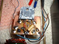
Someone recently mentioned the gain card that attributes it's sound to the tight circuit wiring, not that they use a carbon comp 1/4 W feedback resistor.
Gaicard is quite famous and most copied amp. So many Gain clone around, I built two (not copy of this layout, I haven' seen that photo than), inverting and no inverting and the sound is quite good.
There is big resistor(not feedback) looks like carbon film.
Attachments
Gaicard is quite famous and most copied amp.
It's copied because it's simple. allocating a goodness factor to it is harder.
Edit: checked back on the measurements. It's not BAD from a performance side, but the crippling of the power supply with thin wire and the $3000 price for what is basically a chipamp with added marketing BS did bias me horribly against it and its designer. I am a bad person...
Last edited:
I think a 'short feedback path is important, and resistor quality in that position dominant.
Why dwell on flawed design or lack of understanding?
Because it is neither lack of understanding or flawed design. It is as far as I can tell a design decision!
There are many folks who prefer carbon comp resistors. Last I knew Picasso did just fine.
Last I knew Picasso did just fine.
All speculative, it did look like it could be carbon film anyway, you still think a large body of folks hear this stuff?
And yes $3300 for a $100 BOM, Picasso would approve.
While the gainclone is no bargain, it does have the look of a 'one off', or limited design that would cost more than $100 just for the case and connectors. Let us not exaggerate the 'rip off' to discredit the design.
Last edited:
All speculative, it did look like it could be carbon film anyway, you still think a large body of folks hear this stuff?
And yes $3300 for a $100 BOM, Picasso would approve.
Does look like a 1/8 watt carbon film and mounted where it will get hot. No I don't think most folks would hear the contribution of the single component. But some folks just might.
Now as a guy who can get millions for a sound system, I will not pick on a $3,300.00 dollar amp.
Does look like a 1/8 watt carbon film and mounted where it will get hot. No I don't think most folks would hear the contribution of the single component. But some folks just might.
Now as a guy who can get millions for a sound system, I will not pick on a $3,300.00 dollar amp.
That quality build at 97% margin, you would be picked on.
The Chinese do a better job too, in general. It is just that the sound quality might be variable. Apparently 47 got it to be pretty good.
That quality build at 97% margin, you would be picked on.
If I could get a 97% margin on even a $5,000,000.00 system, I think I could put up with it.
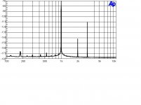
This is what I have on a similar low power carbon film resistor. As resistors go it is one of the worst and probably bad enough it will color the sound to where folks might just hear the contribution of a single part! Distortion looks like -66 on audio, but it is the base spreading showing signal modulated noise that is what I suspect will be the signature sound. It should hide quite a bit.
Attachments
Last edited:
This is what I have on a similar low power carbon film resistor. As resistors go it is one of the worst and probably bad enough it will color the sound to where folks might just hear the contribution of a single part! Distortion looks like -66 on audio, but it is the base spreading showing signal modulated noise that is what I suspect will be the signature sound. It should hide quite a bit.
Care to explain the plot? What/where is the fundamental and how did you get -66dB?
It appears to me the fundamental is at 1KHz. If so, the base spreading is the result of your FFT window selection. Change it, and it will change.
Not that I have any reason to defend carbon film resistors, but why measuring at -70dB fundamental, you feel like getting artifacts at -110...-180dB? The higher the fundamental, the larger the distortions should go.
And here I agonize and beat myself up because my PCB's don't look good enough aesthetically and I know I have to work harder on the electrical layout.
🙁
The fundamental is suppressed. But the resistance value wiggles a bit during the test run so the suppression drops. Better resistors null much better and show the window limits. This one shows base spreading. This test shows the best. Increasing power or lowering frequency raises the distortion. That is how you get -66 when you add in those factors plus the test setup reference. You might want to find the part of this thread where those issues are discussed.
The fundamental is suppressed. But the resistance value wiggles a bit during the test run so the suppression drops. Better resistors null much better and show the window limits. This one shows base spreading. This test shows the best. Increasing power or lowering frequency raises the distortion. That is how you get -66 when you add in those factors plus the test setup reference. You might want to find the part of this thread where those issues are discussed.
Color me blue, I don't understand a thing of what you are talking about, and how you reached the conclusions, but don't bother further. I can live without understanding carbon film resistors.
Waly, you might learn something new here. Ed does a special modification to his SP to get his results. I suspect that this particular resistor measurement did not take any special modifications to show problems, but many resistors that he measured did require that he pre-cancel some of the fundamental to get any useful results. Keep trying!
Waly, you might learn something new here.
I'm sure so; the problem is, I couldn't care less about this sort of "knowledge". I'll leave it to the successful audio designers.
This is what I have on a similar low power carbon film resistor. As resistors go it is one of the worst and probably bad enough it will color the sound to where folks might just hear the contribution of a single part! Distortion looks like -66 on audio, but it is the base spreading showing signal modulated noise that is what I suspect will be the signature sound. It should hide quite a bit.
I could show you some pinch resistors either N or P that are MUCH worse. They just don't go in the signal path, pathological components are amusing just like distortion plots of 741's.
- Status
- Not open for further replies.
- Home
- Member Areas
- The Lounge
- John Curl's Blowtorch preamplifier part II