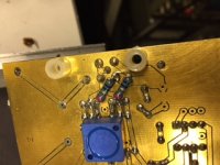
Tacked on resistors are for fine tuning voltage regulators current source and output voltage in Vendetta phono.
Tacked on resistors at the input should be OK. It is impossible to say for sure, because the A was converted to a B, by rewiring the second stage board on the bottom. All resistors should be Resista (banded) or Holco (black).
Voltage changes in the power supply are done with gold plug-in contacts and therefore solderless.
Voltage changes in the power supply are done with gold plug-in contacts and therefore solderless.
Maybe you have not been in DIY long enough, plenty of transformer winders willing to do a custom job for you.
Without giving up a kidney?
Tacked on resistors at the input should be OK. It is impossible to say for sure, because the A was converted to a B, by rewiring the second stage board on the bottom. All resistors should be Resista (banded) or Holco (black).
Voltage changes in the power supply are done with gold plug-in contacts and therefore solderless.
Thanks, John, you saved me a lot of time tracing things out. The jumpers on the back look like wire-wrap wire (don't know what it actually is). If this looks normal to you, I'll proceed assuming that it follows the schematics.
Appreciate your help and the fascinating discussion the past few days.

For the record, the major difference between A and B is that A has a non-inverting second stage, and B has an inverting second stage. The mods in SY's example are factory made.
Question 1, SY. Do you have regulated voltage for each gain block, AFTER the individual cap multipliers?
Now I do, after replacing one pair of pass devices (on the minus rail of the first stage, I used J271). Cap on the output seemed OK, but I replaced it anyway, just to be sure (polypropylene). I'll do signal tracing next, once I get back down to my lab. I basically needed to know if what I had and the schematics were pretty much the same. Since they are, you've saved me a bunch of time tracing out what some modder did.
There's a lot of modders out there who assume they know things that the designer didn't; it's rarely true. So that's why I'm being perhaps overly cautious.
There's a lot of modders out there who assume they know things that the designer didn't; it's rarely true. So that's why I'm being perhaps overly cautious.
Yes, reason why i was thinking DIY=On the shelf.Without giving up a kidney?
Without giving up a kidney?
Could be the market here is better, e.g. with all the transformers manufactured for the yacht/ship industry, but 100% extra charge for a 600VA custom job is fair to me. If it's a small VA size, I just order a dozen or so.
Even Amplimo charged quite reasonable rates for extras.
(I offered my liver, but could keep it, mileage and so on)
voltages
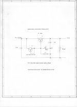
BTW a couple of drafting errors: C2 is reversed, and Q8 is labeled J203 but is shown as a P part. I guess it could be a J203 if it were turned upside down.
On the schematic posted earlier for the SCP-1, what should the regulated voltages be?Question 1, SY. Do you have regulated voltage for each gain block, AFTER the individual cap multipliers?
BTW a couple of drafting errors: C2 is reversed, and Q8 is labeled J203 but is shown as a P part. I guess it could be a J203 if it were turned upside down.
Thanks bcarso, you are correct. This schematic was taken from the internet and drawn by someone I do not know. (reverse engineering), and I can't change it without redrawing it completely, so I must leave it as is.
The supply voltages should ideally be +/- 18V. This is because the servo IC is on this line as well. IF I did it over again, I would separately supply the servo with +/- 15V.
Thanks John.The supply voltages should ideally be +/- 18V. This is because the servo IC is on this line as well. IF I did it over again, I would separately supply the servo with +/- 15V.
Yes I figured the AD711 would be one guide to what the voltages are.
Although I'm confident that the floating current source would only improve noise slightly, I wanted to work through to see how much. Just from the elimination of the resistor noise it looks like about 8%. If one accounts for how much the voltage noise of the cascode transistors' voltage dividers modulate the 249 ohm resistors' currents and refers this to the input, we will pick up some more there as well with the current source. But overall I doubt that the enhancement would run to much more than 10-11%.
I do like the placement of the 75us tau as part of the stage's output load.
Without giving up a kidney?
I think this depends much on where you live, Keantoken. Locally, a 500 VA toriudal transformer, with two separate secondaries to my spec will set me back some €120, or about US$ 145.
But not everyone is that lucky. 😀
Could be the market here is better, e.g. with all the transformers manufactured for the yacht/ship industry, but 100% extra charge for a 600VA custom job is fair to me. If it's a small VA size, I just order a dozen or so.
Even Amplimo charged quite reasonable rates for extras.
(I offered my liver, but could keep it, mileage and so on)
Jac, you being a Dutcman you probably like spicey food and drink Amstel or some such by the hectolitre - and you wonder why your liver is so cheap second hand? 😀 😀 😀
What was the outcome of the JC-2 eBay clone listening tests ?.Well, now what! Run out of questions or solutions? '-)
Dan.
Well, now what! Run out of questions or solutions? '-)
OK. What is the output impedance and how would you lower it for long cable runs or driving lower load Z without increasing distortions?
THx-RNMarsh
- Status
- Not open for further replies.
- Home
- Member Areas
- The Lounge
- John Curl's Blowtorch preamplifier part II