All good points Demian but has nothing to do with RMS or otherwise measurements. You will not measure the line voltage in your home and then size your powersupply to it. Unless you are 100% sure you want to use your equipment only in your room, at that day, at that hour.
Jan
Have you noted the wide variety of reported actual voltages from folks around the world? Quite iffy in some places. That is why you measure your line voltage. Note I have 7 volts more than normal at my shop. Should I allow 10% above that for maximum voltage design?
Knowing what you are starting with gives you a decent window. Demian is designing for world wide use and needs a bigger one.
Or do you want to argue ignorance is better? 🙂
So the question become if Demian has to design for that wide voltage range and can accomplish that is it truly as critical as it seems to be presented? For critical measurements and for lab applications I can see it being important to control the situation but with house voltages being such a wide range, even from house to house how can anyone control that situation and how can a manufacturer build something that would work on only a narrow voltage range? I think Demian has the right idea, you would be amiss if you didn't design a product knowing this is the actual situation, voltages are all over the place.
Now to say that in an industrial situation that the voltage is more consistent is also very questionable in my eyes. If you are a lone user of industrial power from a transformer dedicated to your company that is one thing but in many instances a transformer is a shared resource between multiple businesses and that changes everything. I know I was one who was such a massive power user at one time that I was told by the Edison company that my power draw was affecting everyone down the line when my equipment would put a load on the line. The solution was for the power company to bring in a dedicated transformer especially for my business to limit the ripple down the line. I will say that my neighbor told me that even with my own transformer that his equipment would slow down when my equipment had a large draw, this was a molding operation with multiple high current draws, 85Kw@480 volts on one machine alone plus other high draw equipment that would pull a load simultaneously. My power bill was over $3,000 per month for just the high voltage use and I was a small company in the realm of these things.
Now to say that in an industrial situation that the voltage is more consistent is also very questionable in my eyes. If you are a lone user of industrial power from a transformer dedicated to your company that is one thing but in many instances a transformer is a shared resource between multiple businesses and that changes everything. I know I was one who was such a massive power user at one time that I was told by the Edison company that my power draw was affecting everyone down the line when my equipment would put a load on the line. The solution was for the power company to bring in a dedicated transformer especially for my business to limit the ripple down the line. I will say that my neighbor told me that even with my own transformer that his equipment would slow down when my equipment had a large draw, this was a molding operation with multiple high current draws, 85Kw@480 volts on one machine alone plus other high draw equipment that would pull a load simultaneously. My power bill was over $3,000 per month for just the high voltage use and I was a small company in the realm of these things.
Demian is designing for world wide use and needs a bigger one.
Indeed. Therefore, he makes an educated guess, rather than travelling around the world to do measurements at all his customers' premises.
Jan
Transformer Knowledge Base and FAQ - Toroid - Manufacturer and Designer of Toroidal Power Transformers.
Rod Elliot has a lot to say also.
Dan.
Rod Elliot has a lot to say also.
Dan.
Why not use an SMPS you can then cater for a wide range of voltages and not have to worry...seems to be the standard mode of operation for a lot of commercial gear🙂
Transformer Knowledge Base and FAQ - Toroid - Manufacturer and Designer of Toroidal Power Transformers.
Rod Elliot has a lot to say also.
Dan.
I had to laugh Max.
In a rectifier of the type shown in Figure 1, F has a value somewhere between 1.11 and 5.0 depending on the relative values of the impedances before and after the diode bridge. When these impedances are known, it is possible to calculate F (and UC) using graphical methods published by Schrade in 1943. But at that point the power supply designer usually has in his hand a prototype transformer, so UC and IS can be determined quickly by bench tests. (Be careful to measure IS with a meter measuring true RMS current. Most AC current meters measure Im but are graduated in IRMS, assuming F=1.11 which is only true for sinewave.
Jan DIY is building for ones self and spending money when you don't need to is generally avoided
Scott are you really trying to confuse current with voltage? Or are you just being snide?
Scott are you really trying to confuse current with voltage? Or are you just being snide?
Jan DIY is building for ones self and spending money when you don't need to is generally avoided
Scott are you really trying to confuse current with voltage? Or are you just being snide?
No I guess one needs to read their whole design process, quite complicated. Or maybe just measuring the peak rectified unloaded mains voltage at a given moment is all you need.
I use the same specs Damian does run the variac from 95 to 130 on Radio Shacks finest plug in analog meter. Then Japan has a tap for 100 Volts and you are all set.
Jan DIY is building for ones self and spending money when you don't need to is generally avoided
Come on Ed. Measuring your mains and then selecting a xformer based on that is pretty stupid and you know it. Come back on a Wednesday and it is 5V higher. Or on Friday afternoon it's 6V less.
The ONLY sensible way is to take the max and min specified mains and design your supply to cope with both extremes.
Jan
George,
A center tapped transformer with the center grounded and a pair of rectifiers requires less current than the same with four rectifiers as each winding must now work on the entire power cycle. So the current ratting for a full wave bridge should be twice that for a half wave version.
Ed
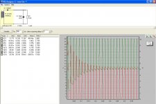
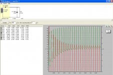
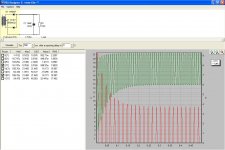
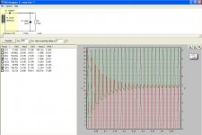
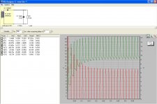
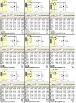
I simulated the psu situation (I have verified results of PSU II with actual measurements many times in the past, so I tend to trust this simple sw). I kept your scenario. 18V rms (nominal) transformer, 1.5A load current, 15000uF capacitor.
The sims show an increase of transformer current with the bridge rectification compared to the FWR (two diodes and a center tap transformer).
The increase is not that dramatic as you say but it is noticeable.
I went a step further and calculated the power supplied by the transformer [P(T1)] and the power consumed by the load resistor [P(R1)].
In all cases [P(T1)]> [P(R1)], thus the ratio [P(R1)] / [P(T1)] I call apparent efficiency.
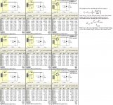
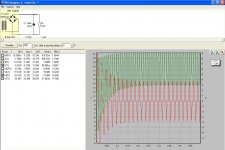
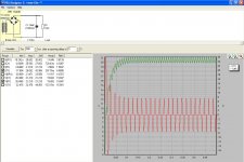
Then I started to look for what else might affect currents and voltages. Two parameters seem to play a role:
a) the transformer’s voltage regulation ( see the following attachments)
Attachments
-
 1 1% tr HWR.JPG136.2 KB · Views: 273
 -
 10 Transf comp.JPG363.3 KB · Views: 68
 -
 9 10% tr BRIDGE.JPG141.2 KB · Views: 61
 -
 8 10% tr FWR.JPG137.4 KB · Views: 71
 -
 7 10% tr HWR.JPG136.9 KB · Views: 64
 -
 6 5%tr BRIDGE.JPG142.7 KB · Views: 67
 -
 5 5% tr FWR.JPG138.7 KB · Views: 269
 -
 4 5% tr HWR.JPG139.2 KB · Views: 255
 -
 3 1% tr BRIDGE.JPG143.2 KB · Views: 277
 -
 2 1% tr FWR.JPG136.4 KB · Views: 265
Last edited:
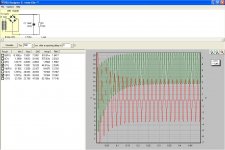
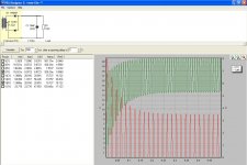
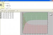
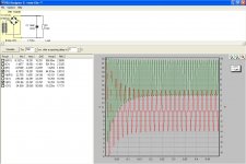
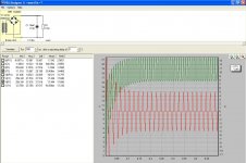
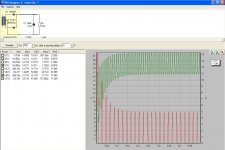
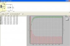
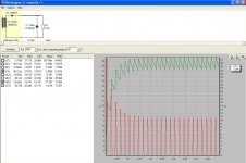
...and b) capacitor’s ESR.
For these simulations I kept the 5% transformer regulation constant and varied the cap ESR.
100mOhm ESR for 15000uf is achievable by paralleling many electrolytic capacitors.
The charging current increase due to that low ESR was a surprise to me.
If this sim reflects the reality, it is not a good practice to place low ESR caps right after the diodes.
Multistage R-C filtering is a very good idea but limited to cases where the load doesn’t change much.
George
For these simulations I kept the 5% transformer regulation constant and varied the cap ESR.
100mOhm ESR for 15000uf is achievable by paralleling many electrolytic capacitors.
The charging current increase due to that low ESR was a surprise to me.
If this sim reflects the reality, it is not a good practice to place low ESR caps right after the diodes.
I would use five 1000 uF @ 50 V capacitors in parallel for the first filter capacitor and then use a pair of 1- 5 ohm resistors to couple that voltage source to a second bank of five more. The increase in filtering will really drop the ripple. So if the junk box transformer is a bit high on voltage, dropping it with resistors is a very low cost method and provides the benefit of not only saving money on capacitors but also reducing heat sink requirements.
Multistage R-C filtering is a very good idea but limited to cases where the load doesn’t change much.
If I would mind gross differencies (which was my initial intention), I would make the following sum-up.
George
Attachments
-
 9 2 Ohm ESR BRIDGE.JPG143 KB · Views: 63
 -
 8 2 Ohm ESR FWR.JPG139 KB · Views: 68
 -
 7 2 Ohm ESR HWR.JPG139.2 KB · Views: 62
 -
 6 1 Ohm ESR BRIDGE.JPG141.6 KB · Views: 62
 -
 5 1 Ohm ESR FWR.JPG131.4 KB · Views: 74
 -
 4 1 Ohm ESR HWR.JPG134.8 KB · Views: 63
 -
 3 100mOhm ESR BRIDGE.JPG133.2 KB · Views: 68
 -
 2 100mOhm ESR FWR.JPG131 KB · Views: 69
 -
 1 100mOhm ESR HWR.JPG131.8 KB · Views: 68
 -
 10 Comp ESR.JPG321 KB · Views: 64
Last edited:
Now if there is even 5% line distortion that transformer will drop low enough that the regulator will run out of headroom. So the next size up would be 18 VAC secondary to work at minimum line voltage. The down side is that under high line conditions your regulator now has double the power to dissipate.
I try to keep 5V minimum btn input-output with the three leg voltage regulators (most of the specs performance plots for these ICs have a note stating the Vin to Vout which is 5V and above).
BTW we wrote the book at least one book
Thank you Scott.
The Crossplot test method described in Appendix A is excellent
Analog Devices
George
Last edited:
Come on Ed. Measuring your mains and then selecting a xformer based on that is pretty stupid and you know it. Come back on a Wednesday and it is 5V higher. Or on Friday afternoon it's 6V less.
The ONLY sensible way is to take the max and min specified mains and design your supply to cope with both extremes.
Jan
Measuring your mains is just basic. Assuming they are nominal when it is so easy to check is silly. Assuming they are rock solid from a single reading is also silly.
And what is the mains voltage where you are?
George
We were talking about a specific mixer power supply. So resistors will probably work well. Not so much for the output stages of a power amp.
Small power transformers often have 10% regulation. Half of that is winding resistance in a typical design.
Out of the office this week when I get back will post real measurements.
Yes 5 volts is much better for typical regulator ICs.
Wayne,
The current standard allows for US line voltage to hit 132 VAC but as that is RMS your 130VAC peak reading should cover that.
The current standard allows for US line voltage to hit 132 VAC but as that is RMS your 130VAC peak reading should cover that.
I work on the basis of considering the mains power to be a complete and utter mess in every way possible, and therefore the job of the audio setup, and not just a particular component, is to isolate itself totally from that environmental misbehaviour - assume nothing. IME this is where some of the really worthwhile gains are made, rather than chasing the last decimal place of low distortion in a particular box of equipment ...
Last edited:
I used to work on some mains disturbance analyers, admitedly they were usually put in place when the customer had a problem with their mains, they had peak impulse measurement using a capacitative divider, often enough the 5KV rated input caps in the divider had failed...
Voltage in the US is pretty good these days clean power is a whole different matter. Good to know that upper limit is 132.
Voltage in the US is pretty good these days clean power is a whole different matter. Good to know that upper limit is 132.
The Standard in the US is to slowly continue to raise the line voltage to reduce line losses. Resistance to changing has slowed down the rate of increase. But many my age remember 117 VAC as the standard. Today it is 120-125 depending on your power supplier.
As has been noted distribution transformers have adjustment trim taps. Either three or five volt steps. So exact voltage kind of gets rounded off.
Interesting that the question started as to which type of meter to use has exploded.
Measuring your mains is just basic. /QUOTE]
Measuring your line voltage for the purpose of designing your power supply is silly. The line voltage has changed by the time you write down your measurement.
Jan
- Status
- Not open for further replies.
- Home
- Member Areas
- The Lounge
- John Curl's Blowtorch preamplifier part II