Simon,
Seriously $450 for that board even having some age? What could you possibly purchase today that would come close that wouldn't cost you much more than that. Geez the Mackey trash for a few channels would cost more than that.
Seriously $450 for that board even having some age? What could you possibly purchase today that would come close that wouldn't cost you much more than that. Geez the Mackey trash for a few channels would cost more than that.
Dan, go and buy a lotto ticket today, it’s your day!
In contrast to people dumping multichannel consoles on the streets, there are people developing and building very interesting projects:
Web Software Defined Radio.
http://websdr.ewi.utwente.nl:8901/
You can operate this radio from your keyboard, listen to what the antenna picks up in Netherlands, scan the RF spectrum and see the traffic, experiment with the IF filters width
George
Simon,
Seriously $450 for that board even having some age? What could you possibly purchase today that would come close that wouldn't cost you much more than that. Geez the Mackey trash for a few channels would cost more than that.
It is a 2200 not 2400. Dealer on the 2400-32 is under 2000USD.
The problem on old boards is the faders. Everything else you can pretty much replace, rotary or slide pots wear out and are tough to match.
There are lots of old used boards around. A new "Digital" 32 channel board is under 2000USD street price.
But fixing one for $50 is certainly worth it.
When the TLO-72 is considered SOTA, we have a problem. Just look at the results that Ron Quan recently put forth at the AES. I am not saying that the '72 is not a 'better' product than a 4558, but not that much better. We are talking about different standards of performance here, between real hi fi and mid fi. There is a difference in my world view.
Dan, go and buy a lotto ticket today, it’s your day!
In contrast to people dumping multichannel consoles on the streets, there are people developing and building very interesting projects:
Web Software Defined Radio.
http://websdr.ewi.utwente.nl:8901/
You can operate this radio from your keyboard, listen to what the antenna picks up in Netherlands, scan the RF spectrum and see the traffic, experiment with the IF filters width
George
George thanks for that link ! ,
right now I listen some Serbian small pirate radio station at1665,41Khz /AM ,it is interesting to see and hear how is radio reception at that relative DX long distance to Netherlands , knowing very well which DIY tube transmitters this Serbian guys use .
I've had several Roku web radio products fail from premature failure of the internal switch mode power supplies. Packed too tightly for proper cooling the larger electrolytics swelled and vented - unfortunately you have to essentially destroy the radios to access the power supply to discover this - so it's non repairable and non replaceable. The ideal product from a manufacturers point of view....
My mid 70's Pioneer TX 9500 with Jung super regulators and redesigned with a discrete jFet analog stage has always sounded better, it just doesn't get as many channels as the Rokus did. ��
My mid 70's Pioneer TX 9500 with Jung super regulators and redesigned with a discrete jFet analog stage has always sounded better, it just doesn't get as many channels as the Rokus did. ��
Last edited:
IC cross-talk
Want to talk about crosstalk in dual and quad IC devices which do not use separate die? [TL072 etal]
View attachment Opamp xtalk.pdf test per Ben Duncan
THx-RNMarsh
Want to talk about crosstalk in dual and quad IC devices which do not use separate die? [TL072 etal]
View attachment Opamp xtalk.pdf test per Ben Duncan
THx-RNMarsh
Last edited:
There is a god.
I made a wish for a mixer so that I can take a critical listen to what a reasonable console actually sounds like in a lounge room reference system....Kazam !.... a serious fully featured mixer that I have copious live mixing experience on.
I also needed a mower, preferably electric....Kazam !....in perfect condition including catcher.
Doesn't matter what's wrong, of course I can sort it.
Thank you.
I will have much fun taking a close listen to throughput from the various inputs and outputs...directs, auxillarys, subgroups, masters, monitor etc etc.
These desks are nicely clean, with good eq section, and features like phase switching and individual channel metering.
These do have a signature sound I reckon, but preferable to Yamaha and Mackie ime/imo
Lounge room listening might be interesting, especially being able to do particular mods to individual input channels and output stages....caps, op amps swaps etc.
I'm still pinching myself that it's real.
All boards incorporate supply series resistors (1R, 10R) and local decoupling, so just about any supply should be good enough.
Yeah, I am expecting some worn faders...this has been a live desk judging by the assignments on the channels.
Overall, it's in well used but pretty good condition.
I expect the SMPS was pulled out for servicing, and that's as far as the repair job got.
I need to visit my junkbox, maybe I can get it running for next to nothing.
Dan.
I made a wish for a mixer so that I can take a critical listen to what a reasonable console actually sounds like in a lounge room reference system....Kazam !.... a serious fully featured mixer that I have copious live mixing experience on.
I also needed a mower, preferably electric....Kazam !....in perfect condition including catcher.
The streets around here are paved with gold.Max,
WTF! They toss an multi-thousand dollar console like that, unbelievable. Good luck with getting it running, probably couldn't have been found by a better person. Have fun.
Doesn't matter what's wrong, of course I can sort it.
Thank you.
I will have much fun taking a close listen to throughput from the various inputs and outputs...directs, auxillarys, subgroups, masters, monitor etc etc.
These desks are nicely clean, with good eq section, and features like phase switching and individual channel metering.
These do have a signature sound I reckon, but preferable to Yamaha and Mackie ime/imo
Lounge room listening might be interesting, especially being able to do particular mods to individual input channels and output stages....caps, op amps swaps etc.
There is an option to replace 5532 balanced outs with SSM2142 balanced out driver ic's.TL072's and NE5532's. Always said the 72's were a star performer when used correctly 😛
Great find by the way
I'm still pinching myself that it's real.
Yeah, on US/Canada eBay, here in Aus I'm seeing $2k.Working it is worth 450 USD. For a power supply you can use IC regulators with a power transistor as a follower. There should be lots of local decoupling of the power supply so basic should work nicely.
All boards incorporate supply series resistors (1R, 10R) and local decoupling, so just about any supply should be good enough.
I did buy a lotto ticket on your recommendation.Dan, go and buy a lotto ticket today, it’s your day!
George
The problem on old boards is the faders. Everything else you can pretty much replace, rotary or slide pots wear out and are tough to match.
There are lots of old used boards around. A new "Digital" 32 channel board is under 2000USD street price.
But fixing one for $50 is certainly worth it.
Yeah, I am expecting some worn faders...this has been a live desk judging by the assignments on the channels.
Overall, it's in well used but pretty good condition.
I expect the SMPS was pulled out for servicing, and that's as far as the repair job got.
I need to visit my junkbox, maybe I can get it running for next to nothing.
Dan.
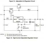
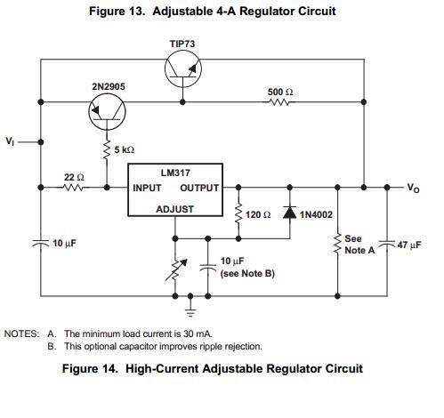
Dan, probably this is what Ed suggests (from TI LM317 datasheet).
For the negative line, use the LM337 with 2N2219 and TIP 74.
George
For the negative line, use the LM337 with 2N2219 and TIP 74.
George
Attachments
Last edited:
Dan, probably this is what Ed suggests (from TI LM317 datasheet).
For the negative line, use the LM337 with 2N2219 and TIP 74.
George
George,
I have seen too many of that design fail. If you substitute modern transistors it may oscillate and even with the older ones, it is not a good thermal design.
But let us start looking at what would be required to produce a 1.5 amp 16 volt supply for Australia. The power is 50 Hz with a minimum voltage of 216 volts AC RMS and a maximum of 253 volts AC RMS.
The minimum voltage across a regulator is typically 2 volts DC. So this would be 18 volts DC into the regulator. Allowing for a full wave rectifier voltage drop of 1.4 volts and a 5% ripple we would require a Peak voltage of 20.4 volts out of the AC power transformer.
Using an Avel made in China toroidal transformer our voltage choices would be 15 volts AC RMS per secondary or 18 volts AC RMS.
Now a 15 volt winding would only have Minimum AC Line Voltage divided by rated Voltage times 15 volts or 216/230 x 15 or 14 volts AC RMS out. This would give a peak voltage of 20 volts, just shy of our target of 20.4 volts.
So the choice would be a unit rated for 18 volts out. Now as we are designing for 1.5 amps peak output that by itself would be just under 60 watts for both windings. As I anticipate loading with a full wave bridge that requires almost double the current capability. So I would pick the model Y236453 that is rated for 120 Volt-Amps at 2 x 115 volt primaries and 2 x 18 volt secondaries.
Now the maximum voltage into the regulator would be 253/230 x 18 x 1.414 -1.2 or just under 27 volts. So there would be a worst case 11 volt drop across the output transistor at 1.5 amps of 16.5 watts of dissipation under maximum non-shorted load. Now if we have no fusing then the worst case power dissipation would be 81 watts per output device.
Now there are some tricks to reduce the ouput device power dissipation and provide other benefits.
Comments so far?
That's why power supply design is not as simple as it looks. Providing for the extreme and managing
I would shop eBay for a Lambda or Acopian supply and move on. It's really hard to improve on those.
I would shop eBay for a Lambda or Acopian supply and move on. It's really hard to improve on those.
That's why power supply design is not as simple as it looks. Providing for the extreme and managing
I would shop eBay for a Lambda or Acopian supply and move on. It's really hard to improve on those.
A DIY project for this will be under $100 for all new parts. It can drop almost to zero with a bit of salvage. Although it looks like two $54.00 Lamdas will also work, except 16 volts is not a standard.
Thanks George.Dan, probably this is what Ed suggests (from TI LM317 datasheet).
For the negative line, use the LM337 with 2N2219 and TIP 74.
George
I was thinking of something along these lines myself.
LM338 is TO-220 variable 5A 3 pin regulator for $20.00 for pack of 5 (local RS Components).
So maybe no need for bypass/helper transistors...can't be more simple ?.
Thanks Ed.George,
I have seen too many of that design fail. If you substitute modern transistors it may oscillate and even with the older ones, it is not a good thermal design.
Now the maximum voltage into the regulator would be 253/230 x 18 x 1.414 -1.2 or just under 27 volts. So there would be a worst case 11 volt drop across the output transistor at 1.5 amps of 16.5 watts of dissipation under maximum non-shorted load. Now if we have no fusing then the worst case power dissipation would be 81 watts per output device.
Now there are some tricks to reduce the ouput device power dissipation and provide other benefits.
Comments so far?
Good to bring up real world conditions, ambient temperature would be my final arbiter, but not a real consideration in my case here.
My thoughts are for now in this case dead simple junkbox parts construction, splurging $20.00 on pack of 5 LM338 TO-220 varable regs.
My mains is usually 252V, right now I am not sure exactly what transformer secondarys I have on my shelves until I measure them.
I am thinking two LM338 in series per rail to give easy adjustment of relative dissipation and wider choice of junked transformers.
The 16V supply spec is not fully tight, I think I saw 15V somewhere.
In any case its a box full of 071 and a few 5534, all isolated by power local series resistor/local bypass cap, so power voltage is not critical, and perhaps supply noise is not particularly critical also.
I also view this as an opportunity to have a play, and see what objective/subjective effects power supply quality has on such a mixing desk.....maybe some surprises ?.
I'm Interested in your comments.
Dan.
Last edited:
George,
I have seen too many of that design fail. If you substitute modern transistors it may oscillate and even with the older ones, it is not a good thermal design.
…
Now there are some tricks to reduce the ouput device power dissipation and provide other benefits.
Ed
Thank you for commending on the circuit.
I am interested on these tricks 🙂
Comments so far?
1. My limited knowledge leads me to think of max transistor dissipation of (VIN − VOUT) × IL) = ((27-15)x1.5) = <20W . Which way do you calculate “81 watts per output device”?
2. I don’t understand the following: “As I anticipate loading with a full wave bridge that requires almost double the current capability”
Do you mean that the use of a full wave bridge loads the transformer secondary with double the current?
I am under the impression that
a) HWR loads the transformer with double the instantaneous (peak charging) current compared to FWR.
b)The average current in either case is dictated by the demands of the load
George
The 81 watt figure is for a fault condition, ie a short on the output, he did say with no fusing...Ed
Thank you for commending on the circuit.
I am interested on these tricks 🙂
1. My limited knowledge leads me to think of max transistor dissipation of (VIN − VOUT) × IL) = ((27-15)x1.5) = <20W . Which way do you calculate “81 watts per output device”?
2. I don’t understand the following: “As I anticipate loading with a full wave bridge that requires almost double the current capability”
Do you mean that the use of a full wave bridge loads the transformer secondary with double the current?
I am under the impression that
a) HWR loads the transformer with double the instantaneous (peak charging) current compared to FWR.
b)The average current in either case is dictated by the demands of the load
George
George,
It is short circuit dissipation of 80+ watts. A center tapped transformer with the center grounded and a pair of rectifiers requires less current than the same with four rectifiers as each winding must now work on the entire power cycle. So the current ratting for a full wave bridge should be twice that for a half wave version.
Nowwhen using a monolithic regulator that can handle the current and is properly heat sunk, the next issue is capacitor size.
The definition of capacitance is C=q/V From this we get C x V = q. As dq/dT is i, we can take the first derivative and get C x dv/dT + V dC/dT = dq/dt = i. As the change in capacitance with voltage is very small we get C x dv/dt = i. For a fullwave bridge on a 50 hertz AC source we can reduce this to C =i/100 x 1/dv. At 5% ripple or about 1 volt we get C= 1.5/100 Farads! (15,000 uF).
So the simple power supply would be a fuse, transformer, fullwave bridge, a pair of 15,000 uF capacitors and a pair of regulators. Now if the transformer has dual windings we can use two bridges and both regulators can be the same! Of course small decoupling capacitors across the input and output of the regulators are probably required for stability.
Now adding a few parts can decrease noise and ripple and actually lower the cost.
I would use five 1000 uF @ 50 V capacitors in parallel for the first filter capacitor and then use a pair of 1- 5 ohm resistors to couple that voltage source to a second bank of five more. The increase in filtering will really drop the ripple. So if the junk box transformer is a bit high on voltage, dropping it with resistors is a very low cost method and provides the benefit of not only saving money on capacitors but also reducing heat sink requirements.
And of course since everyone hates quizes, what is the difference between a peak reading RMS indicating AC volt meter and a true RMS one? Which is more useful for measuring the AC line voltage for use in a linear power supply?
peak reading RMS indicating AC volt meter and a true RMS one?
A crest factor agnostic AC meter, what basis does it use to guess the RMS?
Peak reading rms indicating displays the voltage based on the rms equivalent of the peak voltage of a pure sine wave. TRMS uses some scheme to calculate the heating value of the signal. There are lots of schemes for this.
Perversely the peal reading meter will give a better indication of the DC voltage at the output of the regulator. Just try to explain this to someone who just discovered TRMS meters.
Perversely the peal reading meter will give a better indication of the DC voltage at the output of the regulator. Just try to explain this to someone who just discovered TRMS meters.
- Status
- Not open for further replies.
- Home
- Member Areas
- The Lounge
- John Curl's Blowtorch preamplifier part II