Now, WHY would we want an 'improved' power supply buffer. The most important reason would be when we want the very HIGHEST output swing from the amplifier for the existing output transistors used. Even if we use the 'best' output transistors, we run into 'safe area' problems and potential overheating.
With the existing design, we can just increase the raw power supply voltage, but this will not give us maximum output from the amp, only.
To get a slightly higher voltage swing, we have to do what JBL taught us, almost 50 years ago, we create a separate driver supply voltage, usually practical when we custom build the power transformers for each amp type, but sort of a hassle for DIY'ers.
This way we can create a DRIVE VOLTAGE to the output stage equal or even greater than the output stage can reproduce. This gives us optimum power output. Other 'advantages' can be added as well. (more later)
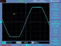
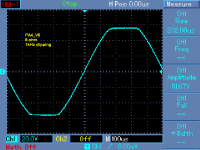
Might be interesting, at the moment, to show VAS maximum voltage swing and maximum output voltage swing of the power amplifier loaded by 8 ohm. Both as clipping. And maximum swing for undistorted output (180W/8 ohm approx.).
Attachments
Last edited:
If we wanted to show a complete schematic, then the Parasound A21 or even the 20 year old Parasound HCA1200 would be even more complete, but intimidating to most of the usual participants of this website.
We're staring at the ground and drooling.
Pavel, it might be interesting to show recovery from overload and what happens on the edges of reactive loading.
We're staring at the ground and drooling.
Pavel, it might be interesting to show recovery from overload and what happens on the edges of reactive loading.
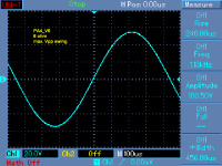
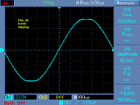
Just a second ago I posted recovery from clipping, is it what you wanted? This topology behaves extremely well.
It's unclear if it's recovery or not. Maybe a tone burst above the clipping point and what you see at baseline immediately after. That's especially interesting with reactive loads having so kickback.
I am taking measurements from my database, right now it is unlikely to measure a new set. It was output clipping without any doubts.
Attachments
Last edited:
Some readers apparently need more schematic to keep them occupied.
Here are 2 examples of Parasound designs that are still available on the used marketplace: I use the 1000 myself. I have used the 1200 as well. They are both 'pretty good' amps, but we can do better.
Here are 2 examples of Parasound designs that are still available on the used marketplace: I use the 1000 myself. I have used the 1200 as well. They are both 'pretty good' amps, but we can do better.
Attachments
The problem we need to address is NOT whether it clips cleanly, but how to get the most 'unclipped' voltage swing from a specific power supply voltage.
My amps, with the same topology can go up to 500W into 8 ohms. THEN, improvements are mandatory.
My amps, with the same topology can go up to 500W into 8 ohms. THEN, improvements are mandatory.
It was output clipping without any doubts.
That part was clear. The question is what happens immediately after? The clipped waveforms into resistive loads look clean, no indication of squegging or sticking, but tonebursts into reactive loads tell the tale. That's one reason that PowerCube (or similar) measurements are very useful for judging commercial amps and diy amps meant for a wide range of speaker types.
The 'PowerCube' measurement of this sort of design was independently tested by 'The Audio Critic' and was found to be near perfect.
Demian, it is some sort of automated test that graphs amp output over power and phase shift in the load. The 'Audio Critic' was the only magazine in my experience to use it.
Demian, it is some sort of automated test that graphs amp output over power and phase shift in the load. The 'Audio Critic' was the only magazine in my experience to use it.
IMO, Absolutely the best way to test an amplfier, no mumbo jumbo ...🙂
Parasound A21:
http://theaudiocritic.com/plog/index.php?op=ViewArticle&articleId=18&blogId=1
Now to yank the protection crap and add larger trafico ...🙂
Last edited:
Mumbo jumbo sometimes works! Good engineering makes it possible to pass the 'PowerCube' test. It doesn't prove that it sounds good.
Last edited:
John, A21 is said to have one 1kW transformer, I use separate 500W per channel, which is again 1kW. Which do you prefer and why, I mean especially regarding HF crosstalk.
- Status
- Not open for further replies.
- Home
- Member Areas
- The Lounge
- John Curl's Blowtorch preamplifier part II