So you do not measure EMI radiation, do not make arrangements to suppress it, you do not measure mess at the output, but just select a 'proper wire', right?
Yes, a single cap may have a specific resonance peak (in fact all caps have that).
The purpose of the additional parallel cap is to lower the first resonance peak, and replace it with a lower one (at higher freq). Then you use another parallel cap to lower THAT resonance and replace it with a lower and higher freq one etc.
But you must know what you do, you must know the parasitic resistance and inductance of the various cap types of course.
If you are interested in this, there a set of very nice articles with graphs on my website by Kendall Castor-Perry (aka the Filter Wizzard).
jan
The rule of thumb has always been, from my memory, a 10:1 in uf value differential, on the film bypass, in order to avoid 'can' resonances building up, in the harmonic sense.
Bruce Moore was seemingly quite good at getting that done correctly. however, even as good as it can be, many have moved away from bypass -entirely.
However, that solution has not always been perfect, as we are back to the original problem, but at least minus the noise of the given solution. The only good part, is that knowledge and recognition of the sonic issue moved the pile forward one notch, via recognition of the audibility of the cure being worse than the problem.
We get a darker sound, but less disruption in harmonic structure of the music signal amplified or whatnot, and thus the music moves people's butts far more effectively.
If using a large bypass due to PS line lengths, a high value (+20uf) EC 5mp12 100vdc film cap (or similar), right on the transistor's rail input leg, works quite spectacularly. No solder, no traces, nothing. metal to metal (anchored by solder), right at the transistor body itself. Lowest impedance pathway that is practical and/or possible. Works for me!
Looks like hell, though.
The problem has always been that people who don't know any better, the buyers, they think that pretty/tidy equipment = quality of audio reproduced.... which is only rarely true.
Last edited:
Picking nits;
Supply decoupling and bypassing. They're different.
IMO decoupling is the crucial element.
Supply decoupling and bypassing. They're different.
IMO decoupling is the crucial element.
IF (and that big IF) it is designed accordingly, it may do so indeed.
Ciao T
Thorsten,
I was for the most part agreeing with you, my only real point is that the by-pass needs to be designed.
If you want a certain minimum impedance then you have to go through the design process to achieve it. This includes taking into account the parasitics and insuring that no resonances exceed the minimum.
A measured response would be required to validate the models and process used.
Thanks
-Antonio
Even before talking of PS requirements i wonder how compensation
is achieved in this amp.
The two lead compensation caps seems to me a risky solution.
At first look , one would conclude that high slew rate was the main
target , at the expense of stability.
is achieved in this amp.
The two lead compensation caps seems to me a risky solution.
At first look , one would conclude that high slew rate was the main
target , at the expense of stability.
The rule of thumb has always been, from my memory, a 10:1 in uf value differential, on the film bypass, in order to avoid 'can' resonances building up, in the harmonic sense.[snip]
Looks like hell, though.
The problem with rules of thumb is that nobody knows why, even if its a wrong rule for the occasion.
And you thought C was C 🙂
jan
Attachments
The problem with rules of thumb is that nobody knows why, even if its a wrong rule for the occasion.
Because it worked well in some different context for somebody else it is now Rule of Dumbs.
The biggest issue is always to dampen transients that result from switching of rectifier diodes. Almost no one cares, though it is well measurable. If not damped, very short spikes get through the amplifier and occur at speaker terminals. On can find them by a fast digital scope in a single shot trigger setting.
These can show up very well on emission testing on the line also. I suspect many small companies don't measure this but I don't know for sure.
About $10K gets a decent EMI test setup for precompliance testing.
What can be measured on a loop of shorted oscilloscope probe ends does not mean it went through the amp being amplified and exists on it's output. It is just an error of measurement that can be improved by fancy cables, ground lifts, other unrelated to sound quality means including super-duper diodes...
John, I'll be out Wednesday and we will officially become neighbors. I'll be at Tilden Park at dawn for some golf you are welcome to join me. I met two 70 yr. old guys who carry their clubs and finish 18 holes in 2.5 hr. amazing. The geezer dawn patrol. Unlike Mayan ball we do not claim the head of the loser.
Short spikes caused by diode switching are coupled into surrounding circuits primary through radiation, not conduction. 500pf in series with a 470 to 1k resistor across each diode in te bridge rectifier fixes it. Also, use fast diodes with soft recovery characteristics - also helps here.
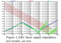
If you feed your power supply through a 50 ohm resistor and then sweep the frequency over say 1k to 5MHz, you may well be able to pick up the resonances. Another option is to feed in a square wave and look for ringing. 1-2 volts is enough and do it directly into the cap bank- ie after the rectifier. If you have a network analyzer, even better. Just for reference, 1cm of PCB trace is c. 10nH, so there's plenty of scope for problems.
Thanks for the invite, Scott. However, I have not played golf for over 50 years. Have a good time, and sometime we will meet together with something more compatible. It is pretty up there.
Short spikes caused by diode switching are coupled into surrounding circuits primary through radiation, not conduction. 500pf in series with a 470 to 1k resistor across each diode in te bridge rectifier fixes it. Also, use fast diodes with soft recovery characteristics - also helps here.
One should also bear in mind the leakage inductance of trafo and how does it involved at diodes switching. Some RC is needed between the AC terminals of the diode bridge. Also, I prefer to build external PS for avoiding electro-magnetic coupling with sensitive parts of the main circuit.
If switching spikes are not suppressed, PS can induce some buzzing sound being approached close to speaker (EMI interaction with driver coil), not saying about EMI effects if PS is inside the amp. Some EMI is produced by the output sections of amp, therfore I prefer SE shunt-like output stage that has no variation of PS current consumption under signal.
Last edited:
Yes - it can cause ringing. This is a big issue in SMPS also where the leakage inductance is much lower, so the ringing is at higher frequencies.
John,
I would note that if one took care to design certain features directly into the mains transformer (including leakage inductance maximisation/compensation) the schematic would look the same (unless we show a detailed equivalent schematic of the transformer) and the power supply filter may be build on a PCB, with precise, designed in trace resistance and inductance filtering and damping resonant tanks.
Sadly I do not remember seeing anything like this in Audio Gear (well, except stuff I design)... This is one area where serious use of industrial methods can give serious improvements with what would seem a generic circuit.
Ciao T
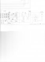
A typical Parasound Amp power supply input.
I would note that if one took care to design certain features directly into the mains transformer (including leakage inductance maximisation/compensation) the schematic would look the same (unless we show a detailed equivalent schematic of the transformer) and the power supply filter may be build on a PCB, with precise, designed in trace resistance and inductance filtering and damping resonant tanks.
Sadly I do not remember seeing anything like this in Audio Gear (well, except stuff I design)... This is one area where serious use of industrial methods can give serious improvements with what would seem a generic circuit.
Ciao T
- Status
- Not open for further replies.
- Home
- Member Areas
- The Lounge
- John Curl's Blowtorch preamplifier part II