Bonsai. 2uF cap in parallel with 4 or 8 ohm really does not say much. It may put current stress on output devices, but does not reveal oscillations. 2uF tends to create RLC ciruit with lead (wire) inductance, nothing more.
To investigate oscillations due to capacitive load, you better try values between 10nF and 200nF.
Regards,
I agree with you on this - I tried these values also.
There are two amplifier manufacturers I am aware of the issue the amplifier design and then look at the warranty returns to decide if they need to beef up the output stage!
Then there is one that has a rigorous testing procedure including running the amplifier at full power into an inductor. Not sure if they changed the process as they have been producing first and second runs of lemons!
Then there is one that has a rigorous testing procedure including running the amplifier at full power into an inductor. Not sure if they changed the process as they have been producing first and second runs of lemons!
RMAF and AES
I just wanted to mention that Cordell Audio and Linear Audio (Jan Didden) will be exhibiting this month at RMAF in Denver and at the AES convention at the Javits Center in NY (Booth 755).
We'll have copies of "Designing Audio Power Amplifiers" and Linear Audio for sale, and would really enjoy seeing you in person.
To get a free Cordell Audio AES exhibits guest pass, just go to:
http://www.aes.org/events/131/vip.cfm?798
Cheers,
Bob
So should we talk a little bit about transformer coupled solid state amplifiers?
I hope so.
I have a schematic but cannot obtain the front end Tx (original was a built to order by Tamura) but I do have the original Tango output Txs. It was based on 2SK135/2SJ50 and had a character which was magical with Classical music! I cannot publish the schematic as it is the IP of another who earns his living in audio.
Any ideas welcome as I would love to get these into my system.
So should we talk a little bit about transformer coupled solid state amplifiers?
The AR amp that went with the circa 1969 dorm room system was transformer coupled.
The AR amp that went with the circa 1969 dorm room system was transformer coupled.
Did it have PNP Germanium output transistors?
Did it have PNP Germanium output transistors?
It might have, don't remember.
It might have, don't remember.
The early transistor amplifiers were designed by guys who were used to vacuum tubes. So they often used driver phase splitter transformers that had a center tapped output to provide bias. Of course with PNP transistors the supply rail was negative.
Attachments
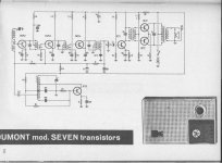
I have a Telefunken radio that I use daily that uses a circuit very similar to this. I have used this sort of radio on a daily basis since 1965, when after a search of quality portable radios, in London, Paris, and finally Munich, I found this particular radio.
It is a Telefunken Bajazzo and is was partially designed by none other than Dick Sequerra.
It sounds very good, MUCH BETTER than you would expect. It has a 'non fatiguing' quality that always surprises me, because sometimes the IM can be almost overwhelming with a low battery or high levels, but it still does not give me listening fatigue. Quite surprising, actually. And yes it has both a driver and output transformer.
I have a Telefunken radio that I use daily that uses a circuit very similar to this. I have used this sort of radio on a daily basis since 1965, when after a search of quality portable radios, in London, Paris, and finally Munich, I found this particular radio.
It is a Telefunken Bajazzo and is was partially designed by none other than Dick Sequerra.
It sounds very good, MUCH BETTER than you would expect. It has a 'non fatiguing' quality that always surprises me, because sometimes the IM can be almost overwhelming with a low battery or high levels, but it still does not give me listening fatigue. Quite surprising, actually. And yes it has both a driver and output transformer.
Mr Curl,
According to data from Antique Radios, 120 000 Antique Radios on display, there are 60 models of Telefunken Bajazzo spanning from 1950 to 1978 !
Can you specify the exact model please? (I am surprised that Dick Sequerra designed for Telefunken).
A large part of the great sound of these radios is to be attributed to their very good large and oval speaker unit.
Regards
George
Attachments

The early transistor amplifiers were designed by guys who were used to vacuum tubes. So they often used driver phase splitter transformers that had a center tapped output to provide bias. Of course with PNP transistors the supply rail was negative.
Looks like they envy some 45's. Valves not records.
Does McIntosh count?
In my life it does in the shape of 50 pounds or more of MC 2105.
vac
The early transistor amplifiers were designed by guys who were used to vacuum tubes. So they often used driver phase splitter transformers that had a center tapped output to provide bias. Of course with PNP transistors the supply rail was negative.
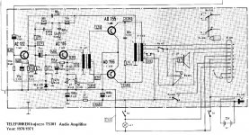
I remember all the little Japanese AM/FM portables (the very small ones - I bit bigger than an iPod - Silver, Hitachi, Sanyo et al) also used transformer coupling - but they did not sound as good as the Telefunken table top portable which we had a a family radio.
The early transistor amplifiers were designed by guys who were used to vacuum tubes. So they often used driver phase splitter transformers that had a center tapped output to provide bias. Of course with PNP transistors the supply rail was negative.
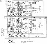
Here is an exception. 😉
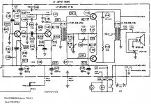
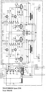
TELEFUNKEN OPUS STUDIO 2650 (Year 1965/68) *.
The audio frequency section built around semiconductors, while the earlier TELEFUNKEN OPUS 2550 HiFi (Year 1964/66) was all tuby
Schematics from Antique Radios, 120 000 Antique Radios on display
* Nominal output 2x15W/4 Ohm (DIN)
Freq. Resp. 40Hz-16kHz +/- 1.5 dB
THD (1kHz, Nominal Output):0.2%
IMD (250Hz/8kHz, 4:1, Full Output): 2%
Regards
George
Attachments
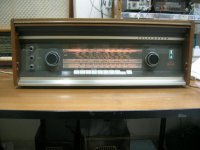
I don't think think was a portable though ('radiogram'?). I saw many of this style Telefunken in my youth.
The audio amp section looks vaguely like a practical wireless amplifer from I think about 1969 or 1970. The PW was built on veroboard or strip board using same AD16x devices and the circuit looks familiar (I am trying to recall back 35 years here). IIRC the PW claimed 10W per channel. Maybe someone has the article.
Wonderful old circuits. Thanks for sharing.
This was the time for transition from transformers to quasi-complementary. Does anyone have any idea what a 2N697 cost in 1965, compared to the other devices? Trust me, plenty!
Last edited:
- Status
- Not open for further replies.
- Home
- Member Areas
- The Lounge
- John Curl's Blowtorch preamplifier part II