Very special case is a JFET follower. But there are another experts on this issue, so I am not disclosing its behavior.
Dennis Feucht spells it out very succinctly. The FETs (J- and MOS-) lack one of the poles that is present in a BJT and is therefore stable as a follower into a capacitive load.
A MOSFET follower can oscillate on its own if the power supply (ie, drain) is not bypassed properly, but that is a different story altogether.
I = DC Current
i = AC Current
V = DC Voltage
v = AC Voltage
j = sqrt (-1)
No one could answer that?
i = AC Current
V = DC Voltage
v = AC Voltage
j = sqrt (-1)
No one could answer that?
I = DC Current
i = AC Current
V = DC Voltage
v = AC Voltage
j = sqrt (-1)
No one could answer that?
I never saw that use of the lower case i and v. In fact physicists and some EE texts prefer i to j.
I never saw that use of the lower case i and v. In fact physicists and some EE texts prefer i to j.
Interesting, that really was first day EE stuff.
I use i everywhere except in circuit equations. But i for current is why j is used!
Sure. Mathematicians and physicists usually use i, and EEs use j. I do not think it is important at all 🙂
Interesting, that really was first day EE stuff.
I use i everywhere except in circuit equations. But i for current is why j is used!
Not important is right, I used I*cos(wt+phi) or the exponential version for AC currents.
Interesting, that really was first day EE stuff.
I use i everywhere except in circuit equations. But i for current is why j is used!
Exactly the way I learned it!
jan
1) the phase shift certainly occurs between the input and output of an emitter follower at high frequencies. You are certainly aware of the well known fact that the follower may oscillate quite happily.
2) regarding gain, please consider that the gain of the follower is the current gain, not voltage gain. It makes no difference which quantity one takes into account and into equations.
Another example, for CFB (current feedback) amplifiers the feedback equations do not use voltage gain and open loop gain, but transfer impedance and open loop transfer impedance.
Good point - its the currents you have to look at.
Oops, I walked straight into that! 😀 I don't have any proofs or suchlike. It was sottomano's persistent nagging that prompted me to think it through and post my conclusions. I guess I should have preceded my entire post with "It seems to me that...".Not at all! We need more posts with facts and figures instead of 'trust me, I know'.
Let's get it right this time:
[IMO]
Yes, looking at the input and output impedances of various stages in an amp can be quite enlightening. It's also a nice way to check the stability of the amp as a whole.I'd also like to add that the output impedance can be analyzed this way...
A lot of people check by testing with various values of capacitor connected across the output. I think it's easier to just check the output impedance of the amp vs frequency. If the phase of the output impedance ever exceeds 90 degrees, the amp will oscillate with some value of capacitor at the output. If the phase exceeds 180 degrees, the amp will oscillate even with a purely resistive load of some value.
Very nice Godrey. I'll drink a Castle to that!
 😉
😉That's an interesting point. If the output impedance of the follower is inductive and the load is capacitive, there will be a resonance and the voltage gain can easily exceed unity.Even if we accept this, there is still a major obstacle to actually seeing the circuit oscillate -- the gain must be greater than one. How can that be?
The circuit below shows this effect. The frequency response looks like what one would expect from an LC low-pass filter.
I see PMA beat me to it with a couple of very nice examples, but I reckon one more won't hurt (especially since I already made the pictures anyway).
[/IMO]
Attachments
Last edited:
So how is intrinsic feedback instead of degenerative for a specific label?
Intrinsic, local, global!
Intrinsic, local, global!
No, intrinsic should be retained for any feedback within a device. For example, a multi-emitter device with built-in ballast resistors.
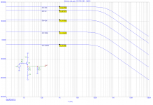
Follower current gain as a function of load resistor (R3):
Pavel, please repeat your simulation using a MOSFET instead of a bipolar transistor.
No, intrinsic should be retained for any feedback within a device. For example, a multi-emitter device with built-in ballast resistors.
Ed has brought up an interesting point. From a marketing standpoint, "intrinsic" feedback sounds more appealing than "degeneration" or "degenerative feedback".
But DF96 objects that the term "intrinsic feedback" should be reserved for those rare devices that have a built-in emitter (source) resistor. I say that this view is incorrect. Every device has "intrinsic" feedback that is equal to the reciprocal of its transconductance. That is to say re. If not for this, the gain of the device (in a common emitter/source configuration without external emitter/source resistors) would be infinite.
Many have posted here about the difference between the external resistor RE and the "internal" resistance re. Some claim that they both constitute "feedback". In that case, we may as well discard the term "feedback", because if every, single device ever made has feedback no matter what the circuit configuration, then it becomes a useless word.
Others claim that the former constitutes feedback, while the latter does not. They have even generated simulations to demonstrate their point. This is an interesting idea and merits further investigation. When we look at the T-model as presented by Feucht (see below), one obvious point is that they form a voltage divider whereby a lower RE results in lower voltage gain.
Slightly less obvious is the RE is essentially fixed, while re varies with the current through the device. In a bipolar transistor this "resistance" varies as the reciprocal of the device current (assuming constant temperature). In a FET it varies as the reciprocal of the square root of the device current.
In normal operation, the device current itself depends almost entirely upon the voltage difference between the two input terminals (base and emitter or gate and source). RE is outside of these two points, which accounts for the difference in the way that RE and re act upon the behavior of the circuit.
We have identified two major differences between RE and re. The variability of re when a signal is present may be minimized by increasing the bias current. For example if the standing current is 100x larger than the peak signal current, then any variation in re due to signal may be ignored. This may be impractical in the real world, but is easily performed in simulation. To minimize the divider action, we may either again increase the standing current (minimizing re) or we may increase the load, RE.
It is interesting to note that both actions are widely acknowledged to improve both measured performance and subjective sound quality. Another way to state this is to say that making re act more like RE results in improved measured and audible performance.
Attachments
Revolution or Mistake
By now most of you have heard about the CERN physicists who have used the Large Hadron Collider to find a particle that travels faster than light does in a vacuum. According to Einstein this is impossible.
Physicist Matt Strassler of Rutgers University sums it up nicely for the New York Times, :
If neutrinos do travel a smidge faster than light, it might mean a rewrite, rather than a scrapping, of Einstein’s theories, Strassler said. “It would still be a big deal, but it might not be a ‘once in every three centuries’ thing.”
Still, physicists allowed that the finding could open the way to a new understanding of the universe. “There’s the chance that it’s a doorway into something fundamental and deep we don’t know about nature,” Strassler said. “All the great revolutions in science start with an unexpected discrepancy that wouldn’t go away.”
Particles faster than light: Revolution or mistake? - The Washington Post
There's something about that last sentence that sounds strangely familiar...
Charles, I don't think there's any scientific breakthrough or revolutions in audio amplifier design, but you've outlined some basic engineering issues with great clarity. Just to throw a bit of a curve, you've distinguished re from RE. Now, suppose the internal resistance weren't between emitter/source/cathode and the outside world, but was somewhere else internal- let's say between drain and gate, but intrinsic to the device. It would then act as a "classic" sort of feedback, right? (You know where I'm heading with this)
But one thing you said puzzles me- making RE more like re to help performance. A sentence or two before, you correctly pointed out that making RE large maximizes linearity, which is kind of the opposite. It's certainly true (in my circuits, I make extensive use of CCS loading to get excellent linearity without loop feedback), but that seems contradictory to the idea of making it small and variable like re.
Am I reading you incorrectly? Or am I missing a more subtle point?
But one thing you said puzzles me- making RE more like re to help performance.
Am I reading you incorrectly? Or am I missing a more subtle point?
Sorry, my mistake. It is too much work to type in all the HTML tags over and over, so I was cutting and pasting. I inadvertently interchanged the two in the sentence you highlighted.
Unfortunately it is too late to go back and edit the post. I hope that this correction ends up on the same page at least, so that someone reading this later won't be too confused by the error. My apologies.
Ed has brought up an interesting point. From a marketing standpoint, "intrinsic" feedback sounds more appealing than "degeneration" or "degenerative feedback".
But DF96 objects that the term "intrinsic feedback" should be reserved for those rare devices that have a built-in emitter (source) resistor. I say that this view is incorrect. Every device has "intrinsic" feedback that is equal to the reciprocal of its transconductance. That is to say re. If not for this, the gain of the device (in a common emitter/source configuration without external emitter/source resistors) would be infinite.
Many have posted here about the difference between the external resistor RE and the "internal" resistance re. Some claim that they both constitute "feedback". In that case, we may as well discard the term "feedback", because if every, single device ever made has feedback no matter what the circuit configuration, then it becomes a useless word.
Others claim that the former constitutes feedback, while the latter does not. They have even generated simulations to demonstrate their point. This is an interesting idea and merits further investigation. When we look at the T-model as presented by Feucht (see below), one obvious point is that they form a voltage divider whereby a lower RE results in lower voltage gain.
Slightly less obvious is the RE is essentially fixed, while re varies with the current through the device. In a bipolar transistor this "resistance" varies as the reciprocal of the device current (assuming constant temperature). In a FET it varies as the reciprocal of the square root of the device current.
In normal operation, the device current itself depends almost entirely upon the voltage difference between the two input terminals (base and emitter or gate and source). RE is outside of these two points, which accounts for the difference in the way that RE and re act upon the behavior of the circuit.
We have identified two major differences between RE and re. The variability of re when a signal is present may be minimized by increasing the bias current. For example if the standing current is 100x larger than the peak signal current, then any variation in re due to signal may be ignored. This may be impractical in the real world, but is easily performed in simulation. To minimize the divider action, we may either again increase the standing current (minimizing re) or we may increase the load, RE.
It is interesting to note that both actions are widely acknowledged to improve both measured performance and subjective sound quality. Another way to state this is to say that making RE act more like re results in improved measured and audible performance.
Hi Charles,
These are very good points that you have made.
The distinction between re and RE is always important. Emitter degeneration is a good thing whether you call it feedback or not. If you call it feedback, it is probably the most benign form of feedback (for those who seek to avoid feedback). In many cases, I like to use 10:1 degeneration, meaning that RE is about 10 times quiescent re. For those who prefer to think of degeneration as negative feedback (I do, but its not a big deal), this corresponds to about 20 dB of very localized NFB.
Cheers,
Bob
- Status
- Not open for further replies.
- Home
- Member Areas
- The Lounge
- John Curl's Blowtorch preamplifier part II