Besides that I think that the formula for ' Siemens '
is (change in current)/(change in voltage)
rather than simply current/voltage
is (change in current)/(change in voltage)
rather than simply current/voltage
Anybody know what 'Hre' is? What about 'Hoe',' Hie' ?
It's either an old skool way of describing transistors or how you get a mule to go left and right. Or maybe something else.
Thanks,
Chris
ps: And don't call me a Hoe.
If the transistor is biased at 1mA, Re = about 25 ohms. If the follower is driving a 250 ohm load, the loop gain is about 20dB.
So by your method, if a bipolar emitter follower biased at 25 mA is driving a 1 megohm load, the loop gain would be 120 dB??? And since the forward gain is ~1, then there would be 120 dB of feedback?
I find that understanding of 'things' like Hoe are important, but the real problem for me is my limitations in putting the exact termonology up with a standard keyboard, such as subscripts. I realize that many here are used to it and have found out how to put up mathematical equations and such, but I am not very interested in working overtime to learn it, myself.
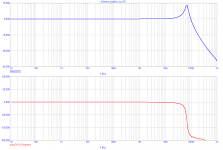
The end result is that if the source impedance and load impedance are both resistive, the loop gain will have a first order roll-off. With a resistive source impedance and a capacitive load, the loop gain has a second order roll-off and you may be in trouble stability-wise. With an inductive source and a capacitive load, the loop gain has a third order roll-off, and you're almost certainly in trouble.
With your "back of the envelope" or "hand waving" explanation, you have shown how you believe that phase shift occurs between the input and output of an emitter follower at high frequencies.
Even if we accept this, there is still a major obstacle to actually seeing the circuit oscillate -- the gain must be greater than one. How can that be?
1) the phase shift certainly occurs between the input and output of an emitter follower at high frequencies. You are certainly aware of the well known fact that the follower may oscillate quite happily.
2) regarding gain, please consider that the gain of the follower is the current gain, not voltage gain. It makes no difference which quantity one takes into account and into equations.
Another example, for CFB (current feedback) amplifiers the feedback equations do not use voltage gain and open loop gain, but transfer impedance and open loop transfer impedance.
I find that understanding of 'things' like Hoe are important, but the real problem for me is my limitations in putting the exact termonology up with a standard keyboard, such as subscripts. I realize that many here are used to it and have found out how to put up mathematical equations and such, but I am not very interested in working overtime to learn it, myself.
John,
That's something that is plagueing me now and then too.
As a way out you could use what we used in earlier times with simple DOS wordprocessors.
We used like R(sub)e or 10(sup)6 for 10^6.
I'm sure people would understand that.
jan
Thanks to all who have helped to clarify things.
Interestingly, even with high feedback values (ccs load) oscillation doesnt always occur, at the other hand i recall an emitter follower as a voltage stabilizer which oscillated with a mostly capacitive input (cap to ground) and a load resistor of 300 ohms, i.e. not that high loop gain.
Interestingly, even with high feedback values (ccs load) oscillation doesnt always occur, at the other hand i recall an emitter follower as a voltage stabilizer which oscillated with a mostly capacitive input (cap to ground) and a load resistor of 300 ohms, i.e. not that high loop gain.
This isn't godfrey's method, just normal circuit theory. Your example will be complicated by things like stray capacitance across the 1M, but given ideal components then yes 120dB OLG and 120dB feedback.Charles Hansen said:So by your method, if a bipolar emitter follower biased at 25 mA is driving a 1 megohm load, the loop gain would be 120 dB??? And since the forward gain is ~1, then there would be 120 dB of feedback?
The loop gain is much greater than one. It is the loop gain which determines oscillation, not CLG. No obstacle, although perhaps counter-intuitive.Even if we accept this, there is still a major obstacle to actually seeing the circuit oscillate -- the gain must be greater than one. How can that be?
Using R_e or 10^6 would make sense to me, and roughly corresponds to LaTeX syntax.janneman said:We used like R(sub)e or 10(sup)6 for 10^6.
Why is it that when typing here, I forget that I can do HTML? I use that stuff all the time on my own website.
The loop gain is much greater than one. It is the loop gain which determines oscillation, not CLG. No obstacle, although perhaps counter-intuitive.
The power gain of an EF is large, that's enough for me.
This isn't godfrey's method, just normal circuit theory. Your example will be complicated by things like stray capacitance across the 1M, but given ideal components then yes 120dB OLG and 120dB feedback.
That is very interesting!
A circuit that has a gain of 1,000,000x with only one transistor!
No wonder it can oscillate with a capacitive load. The amazing thing is that it doesn't just oscillate all the time.
(Please correct me if I'm wrong, but if you have an op-amp with an OLG of 120 dB and power it up with no feedback network in place, won't it tend to oscillate on its own just due to parasitic capacitance from input to output?)
The different forms of feedback are good analogs to each other, but at
the extremes even good analogies tend to fall apart.
😎
the extremes even good analogies tend to fall apart.
😎
...if you have an op-amp with an OLG of 120 dB and power it up with no feedback network in place, won't it tend to oscillate on its own just due to parasitic capacitance from input to output?
Typically, it will slam up to one of the power rails and stick there before it has a chance to oscillate.
The different forms of feedback are good analogs to each other, but at
the extremes even good analogies tend to fall apart.
Then perhaps it's not such a good analogy.
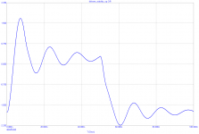
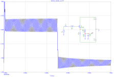
We can sim the follower sensitivity to oscillations when considering real life topology. 1cm of wire or PCB track has inductance of 10nH approx. Following example is quite realistic. The oscillations are damped in this case.
Attachments

Very special case is a JFET follower. But there are another experts on this issue, so I am not disclosing its behavior.
- Status
- Not open for further replies.
- Home
- Member Areas
- The Lounge
- John Curl's Blowtorch preamplifier part II