???? You'd better read through the thread....I ewas asking about the loop gain of an emitter or source follower
No more no less.
No more no less.
ok loop gain =gm x re.Loop gain is approximately gm x Re. I thought that was already clear. Loop gain is whatever you add to 1 in the denominator of the feedback formula. OLG is gm x Re. Amount of feedback is approximately gm x Re.
So...for 2SK170 it's 0.022S x 5Ohm = 0.11x
And Gain = 1
So....OLG =1.11, feedback= err...0.9dB...
Correct?
ok loop gain =gm x re.
So...for 2SK170 it's 0.022S x 5Ohm = 0.11x
And Gain = 1
So....OLG =1.11, feedback= err...0.9dB...
Correct?
5 ohms isn't much of a load for a 2SK170, so gain isn't going to get too close to 1. Maybe try it with 5000 ohms and it'll make more sense.
A way of thinking about the active device is that it's a perfect transconductance with an internal imperfect (non-linear) resistance in the source. That resistance is 1/gm, so for the 2SK170, call it maybe 30 to 50 ohms.
All good fortune,
Chris
Sottomanno is trying to get his numbers right for degeneration, not using 5 R as the load resistor.
Whatever Sottomano is trying to find out, I can't see how it does anything to explain why feedback is good or bad, or how to use it effectively.
It is difficult to respond to such a question, especially when it is not precisely asked, along with diagrams showing what he is looking for.
In my world, I almost always use global negative feedback in the vast majority of my audio designs, from phono preamps to power amps. I really can't understand why some here think that people like me are so 'set against' global negative feedback.
Charles is pursuing a slightly different stratagy. He doesn't use global negative feedback, and either spends extra effort to get the circuit as linear as possible, and just lets the design do what it does, even if some other competing products, (including mine) might measure better in some ways. Charles Hansen challenges us all in the audio marketplace and he often wins. Why this is so, can be partly attributed to the fact that very low measurement specs do NOT necessarily make a circuit design sound better than other products. In fact, often, the opposite is true. This probably has to do with how the ear actually hears, more than anything else.
Now, Harold Black had a DIFFERENT PROBLEM, back in the 1920's and 30's. He needed extra low distortion in order to be able to multiplex multiple telephone calls on one cable and series 100's of amps without exceeding a known distortion budget. Negative feedback was perfect for his needs, but I suspect that the amps he replaced might have sounded just as good, or better than his later designs, if they were used as an audio preamplifier for listening to music in the home, or the recording studio.
What I'm trying to find out?
Some said that emitter degeneration is feedback. Ok, I cannot and do not dispute that. What I wanted to know is, how much feedback do we apply on a follower. It is easily determinable with stages with a loop around them, but a follower?
I wanted to know how much loop gain a follower with different degeneration resistors has. So i can see whether there is some feedback or almost nothing or whatever.
As easy as that.
Last edited:
What I'm trying to find out?
Some said that emitter degeneration is feedback. Ok, I cannot and do not dispute that. What I wanted to know is, how much feedback do we apply on a follower. It is easily determinable with stages with a loop around them, but a follower?
I wanted to know how much loop gain a follower with different degeneration resistors has. So i can see whether there is some feedback or almost nothing or whatever.
As easy as that.
I don't think you can talk about loop gain in an emitterfollower in the sense that you imply.
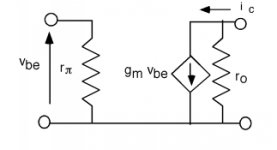
If you look at the attached, and hang an Re off the emitter, I can't really see a loop, although there is clearly feedback visible.
I posted this before:
Vout=Ve= Ie*Re
Ie=(Vin-Vout)*Gm
thus Vout= (Vin-Vout).(Gm*Re)
reworked to Vout/Vin=Acl=(Gm*Re)/(1+Gm*Re), for DC and ignoring base current, no load?
Which approaches '1' for Gm*Re >> 1.
(With Vin between B and gnd, and Re to gnd, and Vout between E and gnd).
For me the feedback factor is the fraction of the output voltage that is fed back to the input voltage which in an EF is 100%.
jan
Attachments
Last edited:
When trying to figure out the loop gain of a common collector stage, it's useful to think in terms of output current rather than output voltage....I was asking about the loop gain of an emitter or source follower
No more no less.
In that case gain = output current / input voltage. In the zero-feedback circuit below, gain is simply 1 / Re. In the second circuit, gain is 1 / (Re + R2). So gain has been reduced by a factor of (Re + R2) / Re. The feedback factor (or loop gain) is about the same, depending on your definition and pickiness about the exact math.😀
I appreciate that the zero-feedback circuit would be completely useless, but it is generally recognized that emitter followers have "a lot" of voltage feedback. Thinking about it this way lets you quantify that better.
E.g. If the transistor is biased at 1mA, Re = about 25 ohms. If the follower is driving a 250 ohm load, the loop gain is about 20dB.
Attachments
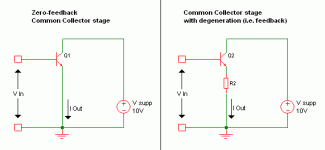
When trying to figure out the loop gain of a common collector stage, it's useful to think in terms of output current rather than output voltage.
In that case gain = output current / input voltage. In the zero-feedback circuit below, gain is simply 1 / Re. In the second circuit, gain is 1 / (Re + R2). So gain has been reduced by a factor of (Re + R2) / Re. The feedback factor (or loop gain) is about the same, depending on your definition and pickiness about the exact math.😀
I appreciate that the zero-feedback circuit would be completely useless, but it is generally recognized that emitter followers have "a lot" of voltage feedback. Thinking about it this way lets you quantify that better.
E.g. If the transistor is biased at 1mA, Re = about 25 ohms. If the follower is driving a 250 ohm load, the loop gain is about 20dB.
Thanks Godfrey, that clears up things for me.
I do want to note though that your Re is the 'internal' emitter resistor (1/Gm) while in my posts I have used Re for the external emitter resistor, which in your 2nd circuit is R2.
jan
Yes, thanks for pointing that out Jan.
To continue....
This allows us to do "distortion vs feedback" calculations in much the same way as with other circuits.
E.g. If you have an emitter follower with an idling current of 1mA driving some or other value of load resistance, you might want to halve the distortion by adding another 6dB of feedback. To do that, you need to increase the open-loop gain by 6dB, and to do that you need to halve the intrinsic emitter resistance by increasing the idling current to 2mA.
~~~~~~~~~~~~~~~~~~~~~~~~~~~~~~~~~~~~~~~~~~~~~~~~
I can't get excited about that kind of thing, but what I do find interesting is that it can also give quite a clear insight into stability considerations for followers. Suddenly "mysterious" oscillations aren't so mysterious and avoiding them becomes less of a black art relying on folk remedies such as "putting a coil on the output usually works" or "you might have to add base-stopper resistors", which leave a lot of folks not having any idea how to calculate appropriate values and either just copying what somebody else did or figuring it out by trial and error.
~~~~~~~~~~~~~~~~~~~~~~~~~~~~~~~~~~~~~~~~~~~~~~~~
To do this kind of analysis, we need to take into account a couple of second-order effects. Doing that we get something like:
Open loop gain = output current / input voltage
= 1 / (intrinsic emitter resistance + (intrinsic base resistance + source impedance) / current gain)
So at high frequencies, where the current gain is rolling off at 6dB per octave, the open loop gain is also rolling off at 6dB/oct. If the source impedance is inductive, the open loop gain will be rolling-off at 12dB/oct at high frequencies.
Now if the load is resistive, the demanded closed-loop gain is frequency-independent. However, if the load is capacitive, the demanded gain is increasing at 6dB/oct.
The end result is that if the source impedance and load impedance are both resistive, the loop gain will have a first order roll-off. With a resistive source impedance and a capacitive load, the loop gain has a second order roll-off and you may be in trouble stability-wise. With an inductive source and a capacitive load, the loop gain has a third order roll-off, and you're almost certainly in trouble.
Anyway, the point is that looking at followers this way allows you to plot gain and phase vs frequency for the open-loop gain, closed-loop gain and loop-gain (or feedback factor).
😱Sorry for overly long post.
Last edited:
Don't be sorry. That was very clear and useful, and I say that as one of those "might" and "usually" guys! 
[snip]Anyway, the point is that looking at followers this way allows you to plot gain and phase vs frequency for the open-loop gain, closed-loop gain and loop-gain (or feedback factor).
😱Sorry for overly long post.
Not at all! We need more posts with facts and figures instead of 'trust me, I know'.
jan
Yes Godfrey thanks,
I'd also like to add that the output impedance can be analyzed this way, and for most biases, shown to be increasing (inductive) with frequency (between limits).
Gray and Meyer "Analysis and Design of Analog Integrated Circuits" really gives some good insight, as it does for the general feedback analysis including Local Series Feedback or Emitter Degeneration.
Thanks
-Antonio
[snip]Gray and Meyer "Analysis and Design of Analog Integrated Circuits" [snip]-Antonio
Ahummm... $ 150 🙁
jan
When trying to figure out the loop gain of a common collector stage, it's useful to think in terms of output current rather than output voltage.
In that case gain = output current / input voltage. In the zero-feedback circuit below, gain is simply 1 / Re. In the second circuit, gain is 1 / (Re + R2). So gain has been reduced by a factor of (Re + R2) / Re. The feedback factor (or loop gain) is about the same, depending on your definition and pickiness about the exact math.😀
I appreciate that the zero-feedback circuit would be completely useless, but it is generally recognized that emitter followers have "a lot" of voltage feedback. Thinking about it this way lets you quantify that better.
E.g. If the transistor is biased at 1mA, Re = about 25 ohms. If the follower is driving a 250 ohm load, the loop gain is about 20dB.
Very nice Godrey. I'll drink a Castle to that!
More terminology. RE external emitter resistor Re internal modeled resistance. Capital letters mean static, lower case dynamic.
- Status
- Not open for further replies.
- Home
- Member Areas
- The Lounge
- John Curl's Blowtorch preamplifier part II