To complete the power supply, I think that the 78/79L15 regulators would work (barely), and I would like any suggestions for something JUST AS SIMPLE, but maybe better.
The only thing that comes to mind is a passive RC cascade but it needs some decent sized elcaps so it may be more expensive.
What could work better is a modified cap multiplier that also holds the voltage steady.
One bipolar, 1 resistor, 2 elcaps and 8 cheep red Leds per polarity.
What could work better is a modified cap multiplier that also holds the voltage steady.
One bipolar, 1 resistor, 2 elcaps and 8 cheep red Leds per polarity.
Here is my circuit, positive version. When you use 2mA Leds they can be ignited as low as 0.5mA. Then the resistor shoud be around 5kOhm. We could use two 6.2V Z diodes in series instead.
Another option is the TL431CLP that costs 15 Euro Cent or the LM Micropower Voltage References from National that draw realy minimum current. We have to supply the base current though. If the OPA4134 draws 20mA to 30mA the high Hfe BC550C-560C will draw aproximately 1/500th of that.There are some C-E losses too but i am too tired at the moment to calculate hat.
Holding Vce at a very low value slightly over cutoff ( 0.2V ? ) whould minimise that.
Attachments
Well, that low Vce is not posible in that circuit. Sorry, i am not 100% functional at the moment. I was very busy today. Setup 3 systems at friends.
Ok, last try, it´s simple. We loose 2V over the transistor. The OPA4134 draws aproximately 25mA. We burn 50mW in the transistor from collector to emitter.
The Leds waiste 8 x 1.7V x 0.5mA = 6.8mW. The base current is neglectible.
Good night, i may meet you tomorrow.
The Leds waiste 8 x 1.7V x 0.5mA = 6.8mW. The base current is neglectible.
Good night, i may meet you tomorrow.
Joachim, it would work, but 3 X 5.1V zeners would do just as well, AND with less parts. Why do we need to be so quiet? Is it really necessary? Check it out. There is such a thing as power supply rejection. In any case, a simple 3 terminal regulator is the most simple, then a SIMPLE cap multiplier could be added to lower noise still further. No hum, no noise, no power supply 'breathing' and line pop protection too, with current limiting.
Last edited:
PSU
PSU: We need +/- 15 VDC @ 20 mA.
15VAC wall wart transformer. Ground one secondary phase. Two 1A diodes, two 1000 uF capacitors. 78L15 and 79L15 regulators. Two small output caps, 22 uF or so (79xx regs oscillate if not decoupled).
Thats it!
This design could be refined with RF damping of diodes, protecting diodes etc, but that is outside the simplest approach.
LM317/337 are about 20 dB better than 78/79 series regs. But the price tag is almost double. And of course there are even better regs. But the data sheet for the chosen opamp tells us that this is not needed.
Looks like this thread may give birth to a worthy NAD PP1 contender. How on earth did this happen?
PSU, afterthought I
Worst case power loss may approach 300 mW per regulator. So it might be an idea to use the TO-220 part instead of the TO-92 "L" version.
Worst case power loss may approach 300 mW per regulator. So it might be an idea to use the TO-220 part instead of the TO-92 "L" version.
Last edited:
Looks like this thread may give birth to a worthy NAD PP1 contender. How on earth did this happen?
Even Volks-Wagen counts 😉

It should be possible to keep the L version, because the regulators are temp protected. Good engineering, 2quad.
Everyone, please remember, this is an ENGINEERING EXERCISE, not an audiophile statement.
My latest JC-3 phono stage made the NY Times, today. It is certainly more complex than this engineering exercise, and it costs 20 times as much, retail, as this simple unit would, if made by Sony or an equivalent company.
My $40,000 super project humbles both efforts, significantly, being up to 25 times quieter, etc, etc.
PSU design & simulation
I chose a local vendor for wall wart:
http://www.mascot.no/?CatID=1179
The data sheet for their 15Vac 8.5VA wall wart model 8510 shows a idle voltage of 18 volts and 15 volts into 0.5 amps. This translates to a Thevenin source of 18 volts in series with 6 ohms.
I simulated the circuit in SwCAD III using 30 mA load current. Attached are the schematic and the transient analysis.
The current from the transformer peaks at 340 mA. Checking with 10% drop in voltage shows that the minimum DC voltage still is high enough for the regulators (i.e. more than 3 volts above their output voltage).
Attachments
Last edited:
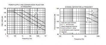
Just for completeness, here is the PSU rejection chart of the OPA4134 and the crosstalk chart. PSU rejection to the negative supply is better so we could tie a 5kOhm resistor from output of the lineamp to the positive supply. Then it runs in class A up to 3mA and we may get a better PSU rejection. Using Opamp A and B for the Phono and C and D for line we can get better crosstalk.
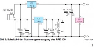
See also an alternative floating supply, this time with the regulators in series. This example gets only plus-minus 5V, so it has to be modified.
See also an alternative floating supply, this time with the regulators in series. This example gets only plus-minus 5V, so it has to be modified.
Attachments
- Status
- Not open for further replies.
- Home
- Member Areas
- The Lounge
- John Curl's Blowtorch preamplifier part II