The shunt regulator in the CTC Blowtorch has a second function, which is to damp any high frequency transients that might escape the first regulator. It is open loop, simple, and very fast.
Not when the series regulator following the shunt one is a capacitance multiplier – not as far as supply ripple is the issue. With class A amps, the extra inner impedance of the capacitance multiplier is a lesser issue than ripple value. Now, shunt regulators have benefits other than including the return in the regulating chain.
Your series reg after the shunt will be worse than the shunt - there's no improvement, max you get is same. Do the math.
jan didden
CTC Blowtorch is, I believe, Class A, therefore no varying load for the regulator.
You believe wrongly. Check the current varriations in each supply line.
But I don't want to argue this anymore.
Have a great day.
jan didden
Jan, in the CTC Blowtorch the current changes are almost unmeasurable, because it is a class A, complementary differential folded cascode stage that forces the current to be constant at all times to a first order approximation.
Last edited:
In a series reg, the return current goes back to a capicitor at the reg output. That means it goes through some traces or wire. This same wire or trace will carry return current from other stages or other parts of the (pre) amp. So there is coupling between stages through the voltage induced on the return leg, and that induced voltage is generally distorted, but also can be seen as part of the input signal.
In a shunt reg, the return current doesn't go back to the supply but is part of the shunt current which varies with the load current.
Yes a schematic would be nice ;-)
jan didden
Fireworks,
Are you comfortable with my explanation? If not, we can discuss this further.
jan didden
Thanks PMA, of course, the CTC line stage is somewhat of an exception. Many OP amps and most discrete designs would have more variation in current with audio signal.
I use the shunt regulator in the CTC primarily as a transient eliminator, as I have measured the multi-MHz bleedthrough that happens with standard IC regulators. In fact they are virtually 'AC shorts' in the MHz region. It has been shown by an IBM paper published in the IEEE a few years ago, that power line garbage can extend to 50 MHz or more, just from electric stoves, so I thought that I would cover that area as well.
I use the shunt regulator in the CTC primarily as a transient eliminator, as I have measured the multi-MHz bleedthrough that happens with standard IC regulators. In fact they are virtually 'AC shorts' in the MHz region. It has been shown by an IBM paper published in the IEEE a few years ago, that power line garbage can extend to 50 MHz or more, just from electric stoves, so I thought that I would cover that area as well.
No shunt will help at "multi-MHz bleedthrough", neither discrete based, neither opamp based with >1GHz and XXXX V/μs. When error amp run out of steam, all rejection left is based on CCS pass element. Your best friend there are small package ceramic caps & ferrite beads.
No shunt will help at "multi-MHz bleedthrough", neither discrete based, neither opamp based with >1GHz and XXXX V/μs. When error amp run out of steam, all rejection left is based on CCS pass element. Your best friend there are small package ceramic caps & ferrite beads.
Indeed, a shielded RF filtering at the mains entrance would be useful. One measure doesn't exclude the other, each has its' own benefits and merits.
Yes, the BT supply current is almost constant.
Pavel what's the load R on that simulation?
jan didden
Jan,
In a balanced Class A circuit like the Blowtorch, the supply current is really very close to constant.
This is only true for balanced, not single ended.
I am speaking from experience.
I'll explain to you when we get to meet, in November perhaps ?
Patrick
In a balanced Class A circuit like the Blowtorch, the supply current is really very close to constant.
This is only true for balanced, not single ended.
I am speaking from experience.
I'll explain to you when we get to meet, in November perhaps ?
Patrick
John also mentioned that the folded cascode architecture was used. In most implementations of folded (shunt) cascode, the supply current is constant in instantaneous or average measurement, and this is true of SE or differential designs - again, for most implementations.
I use shunt cascode arrangement for almost all gain stages, even with triode-connected pentodes. The supply-rejection and common-mode rejection are way ahead of any other methods, and the supply current is entirely constant.
I use shunt cascode arrangement for almost all gain stages, even with triode-connected pentodes. The supply-rejection and common-mode rejection are way ahead of any other methods, and the supply current is entirely constant.
Anyone may check topology shown in
http://www.diyaudio.com/forums/anal...rch-preamplifier-part-ii-643.html#post2348253
and supply current value as well (high idle current of output current source like connected MOSFETs). I assume no word description is needed 🙂
http://www.diyaudio.com/forums/anal...rch-preamplifier-part-ii-643.html#post2348253
and supply current value as well (high idle current of output current source like connected MOSFETs). I assume no word description is needed 🙂
Stormsonic, I already use low leakage E-I transformers, a pi network composed of 3 elements, including a common mode choke, before the first regulator, but there is that area between 100KHz and 10MHz where the power most fet is still active as a shunt, working against a 10 ohm resistor. My explanation about the behavior of the standard 317-337 regulators is more for general understanding of a potential problem in a number of circuits, especially digital, not just the Blowtorch.
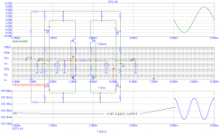
1k output load impedance is a MUST for this design to work. It is a part of the circuit. With additional load the supply current would be more constant, BUT voltage gain would decrease. This is a current output amplifier and output voltage is created on 1k resistors in both + and - branches.
Yes, the BT supply current is almost constant.
OK, so with the 1k load, and 8V peak Vout, I would expect 8mA peak supply current variation.
Which is exactly what your sim shows.
So it appears that the supply current variation is exactly the same as the load current; in other words the load current is reflected in the supply 1:1. Whatever this circuit does, it does nothing to supress supply current variations.
Your statement that it 'does have very little supply current variation' or words to that effect is wrong.
jan didden
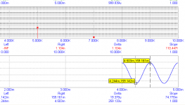
Where have you read this?? (8mA supply current variation). It is about +/- 0.01mA. For a clever guy like you, I would assume more circuit theory understanding.
Attachments
John, as humble DIYer I'm grateful for opportunity to learn from famous audio designer.
Just pointed out that shunts are far better than 317 and other 3-pin regulators, but they are not almighty.
Just pointed out that shunts are far better than 317 and other 3-pin regulators, but they are not almighty.
Where have you read this?? (8mA supply current variation). It is about +/- 0.01mA. For a clever guy like you, I would assume more circuit theory understanding.
You are correct, I misread the scale. Sometimes I'm too clever for my own good 😉
jan didden
- Status
- Not open for further replies.
- Home
- Member Areas
- The Lounge
- John Curl's Blowtorch preamplifier part II