Techs with MP3s should be shot!
Regards, Allen
I have found a worse punishment... they work for me.
Power supplies (part 2)
It can be asked, 'Well, if we have a problem with cap input, why don't we convert to choke input?' Well, they used to do it in some equipment, perhaps 80 years ago, and still sometimes do, up to the present, BUT choke input gives you as many problems as it addresses, as it can be VERY UNSTABLE, if you are not careful, and even blow up your power supply caps. However, in an ideal world, with virtually pure class A amp operation, as many modern tube amps have, and care taken against current change through the choke, this can be one of the finest power supply approaches available.
What happens, however, if you try to make a choke input supply for power amp that is NOT class A, but class AB or class B for all practical purposes? Well, the choke size gets HUGE. Pretty soon, the choke is BIGGER than the power transformer. Do the math, yourself, if you can, or just believe me, if you can't. The other major problem is that you MUST maintain a certain MINIMUM CURRENT across the choke, in order to get it to put out the rated voltage. If you remove the current, the voltage will virtually double and blow up your load caps, as well as you amp, if it is still connected. Therefore, a sophisticated protection clamp may be necessary for this potential problem. It gets expensive, but this is still a good design choice for an all-out class A design. Now, what about the vast majority of solid state power amps? (To be continued.)
Smoothing choke or swingin' choke?
Count Basie was into swing, but that's a differn' thang!
_-_-bear
Count Basie was into swing, but that's a differn' thang!
_-_-bear
Power supplies (part 2.5)
Bear brings up an important approach to choke input power supplies. Namely, using a swinging choke, rather than a linear choke. This is an inductor that is designed to be very high inductance with low DC current passing through it and lower inductance at high current levels. It is a compromise, in order to save space, weight, and still have decent regulation. It is an interesting choice, BUT if you disconnect the power supply for any reason from the load, you can still get excessive voltage that could blow up the power supply caps. This is a good way for the really high end designer to go, if they wish.
Bear brings up an important approach to choke input power supplies. Namely, using a swinging choke, rather than a linear choke. This is an inductor that is designed to be very high inductance with low DC current passing through it and lower inductance at high current levels. It is a compromise, in order to save space, weight, and still have decent regulation. It is an interesting choice, BUT if you disconnect the power supply for any reason from the load, you can still get excessive voltage that could blow up the power supply caps. This is a good way for the really high end designer to go, if they wish.
This months AudioXpress is a particularly interesting issue. First they have not wasted any space on my drivel and secondly there is an article showing the change in processing delay over the course of a single cycle for both a gain clone and a tube amp.
This months AudioXpress is a particularly interesting issue. First they have not wasted any space on my drivel and secondly there is an article showing the change in processing delay over the course of a single cycle for both a gain clone and a tube amp.
Simon, AX is always interesting, even with your stuff in it 😉
But seriously; are you referring to fig 1 & 2 in that article?
jd
Simon, AX is always interesting, even with your stuff in it 😉
But seriously; are you referring to fig 1 & 2 in that article?
jd
😉=Humor
Yes, the changing delay is most interesting.
I will try to confirm his results as I have some gain clones.
😉=Humor
Yes, the changing delay is most interesting.
I will try to confirm his results as I have some gain clones.
Simon, I'd be curious to your findings.
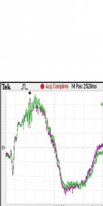
I cannot see any delay in Figs 1 & 2. The plots don't support that.
If you look at some tell-tale peaks on the waveforms that can be used for reference, for instance at the bottom of the negative-going part of the waveform, or just to the left of the zero crossing, it is clear that in both cases the waveforms line up EXACTLY. There is NO delay visible (which would be difficult to see anyway at a 1mS/div scale). There is only a level difference.
jd
Power supplies (part 3) Now we come to what I wanted to talk about in the first place, pi filter power supplies, updated from the old days, to solve specific problems that we have indirectly generated by improving other aspects of power supply function.
This type of power supply promises to lower peak current drawn from the AC wall outlet, utilize the power transformer more efficiently, and still allow for a very good ground return, and excellent regulation. Though not as good at transformer utilization as the full choke input, the pi filter could significantly improve the situation and never be conditionally unstable, like the choke input can well be.
This filter would be comprised of 3 major components: An input cap (probably somewhat smaller than the output cap), a choke, swinging choke, or perhaps a common mode choke, and an output filter cap that would most closely resemble the conventional output capacitance used normally.
The choke is the most unconventional component in this type of power supply. In the past, specific chokes up to 5H or so were designed and used in tube power amps, but a SCALED choke with 100 times more current capability, 100 times less series resistance, and still some useful inductance is not commonly available, because there has been little or no need for one. If anyone out there knows of a good candidate, please submit it here.
Lastly, a large common mode choke MIGHT be a rational choice for this component, as it would be significantly smaller and lighter, due to the fact that the DC components of the positive and negative supplies could cancel and keep a relatively small choke from saturating. However, there may be hidden problems, that I, at least, have never looked at, when it comes to a large power amp that should be noted.
This exercise is not to greatly increase the cost of the power supply design, but to make it more practical in the real world of today. I think that this approach might be less problematic than form factor circuitry that could add as much garbage to the amp sound, as do switching supplies, in general.
When I look at this I see the waveforms start out at the same time then the green trace begins to lag. If you shift the trace to match levels the lag gets worse. I do not know if this is an artifact of how the waveforms were sampled. I just find it interesting.
When I blow this up I see some spikes have shifted by a few pixels.
When I blow this up I see some spikes have shifted by a few pixels.
Attachments
Last edited:
Lastly, a large common mode choke MIGHT be a rational choice for this component, as it would be significantly smaller and lighter, due to the fact that the DC components of the positive and negative supplies could cancel and keep a relatively small choke from saturating. However, there may be hidden problems, that I, at least, have never looked at, when it comes to a large power amp that should be noted.
I see a potential problem with a common mode choke if the star ground it connected to the transformer center tap. If trying choke, I would favor a bridge on each secondary, and not ground PS until after the final caps. But I would do this, anyway, whether or not choke is used.
I work with Sowter and they are very flexible. When i have the spec. i could ask Mr.Sowter if he can design a choke for poweramps.
I also heard that putting a small resistor ( say 0.5Ohm) between two fiter caps improves ripple rejection much compared to a bigger cap with the same value then the two combined.
I also heard that putting a small resistor ( say 0.5Ohm) between two fiter caps improves ripple rejection much compared to a bigger cap with the same value then the two combined.
Yes, that forms a really good RC filter with a very low cutoff frequency of about 10Hz. In conjunction with high speed rectifiers probably the best (and most simple) solution to get rid of hum and noise from the power supply.I also heard that putting a small resistor ( say 0.5Ohm) between two fiter caps improves ripple rejection much compared to a bigger cap with the same value then the two combined.
I work with Sowter and they are very flexible. When i have the spec. i could ask Mr.Sowter if he can design a choke for poweramps.
I also heard that putting a small resistor ( say 0.5Ohm) between two fiter caps improves ripple rejection much compared to a bigger cap with the same value then the two combined.
Putting two identical capacitors in parallel would halve the ripple.
A typical 22,000uf capacitor at 120 hertz would have an impedance of .06 ohms.
20Log (.06/.5)=-18.4db. A big improvement
Putting two identical capacitors in parallel would halve the ripple.
A typical 22,000uf capacitor at 120 hertz would have an impedance of .06 ohms.
20Log (.06/.5)=-18.4db. A big improvement
Using 2 capacitors of the same make in parallel, say 2 x 10,000uF instead of 1 x 20,000uF will improve also the ESR.
I also heard that putting a small resistor ( say 0.5Ohm) between two fiter caps improves ripple rejection much compared to a bigger cap with the same value then the two combined.
RC filter is a single-pole filter.
LC filter is a two-pole filter. Sharper cutoff than RC filter.
I'm wondering how drastic the emission from a choke would be inside the chassis. Them charging currents are pretty high and short. The chokes would help smooth the spikes, but I would think they would have to be isolated from the amp circuitry in some way, and not just distance or orientation.
IME, CLC like that works fine providing L is picked so that ESR of the caps make the whole at least critically damped. Air-core inductors of around 10uH are easily handwound; Z= SQRT(L/C) = SQRT(10uH/10000uF) = ~30mR, comparable with the ESR of such caps...LC filter is a two-pole filter. Sharper cutoff than RC filter.
Even such tiny L puts the filter knee at just 500Hz, low enough to be quite useful.
Last edited:
- Status
- Not open for further replies.
- Home
- Member Areas
- The Lounge
- John Curl's Blowtorch preamplifier part II