Returning to the SF hi fi show, this last weekend: Apparently, the big hit of the show was the use of ANALOG TAPES as the source for a couple of quality set-ups. If you think that vinyl records are exotic, just wait till we return to analog tape recording! In truth, they can sound awfully good. The only thing that ever beat it, in my opinion, is direct disc recording with carefully designed support equipment. I realize that most here will probably never hear quality all analog tape playback ever again, being that it costs plenty to do, and the source material is minimal, but it again shows 'me' that digital just isn't 'perfect sound forever' even after almost 30 years of perfection following its appearance for the masses. It seems that even when you throw 'everything in the book' at it, it still does not come up to analog sources.
I know.
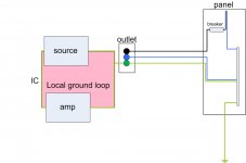
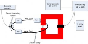
The output jack has a signal terminal and a ground terminal. When a 1 volt signal is generated, the signal terminal will have 1 volt to the internal ground. The differential receiver input will see that 1 volt to it's own internal ground reference, so it will draw current from that signal line, and that current will go to chassis internal ground.
In other words, the IC is being tested as a simple loop of wire with NO effective shield other than a faraday extension.
This is why the test setup is extremely sensitive to external fields as well as sensitive to the wire placement, as the test instrument has no ability to cancel any loop trapping generated voltage cause by the test cable in the environment. The setup design does not use the coax as a coax..
Once the ground loop is broken by a transformer, the current in the core of the coax will go through it's resistive load at the receiver (+) input to the chassis ground connection, and then it will go through the (-) input's resistor and back through the shield to the output transformer. Instead of the current topology where the shield has NO current at all, and the return current flows through the internal chassis ground.
As for capacitive coupling, there are methods to lower that. Apparently AP has done so.
Cheers, John
The semantic issue is "uncontrolled" current path. I would use different language.
Your argument is that the "aggressor" noise is electromagnetic, not electrostatic. If I follow this then the voltage induced in the cable will be the same on the shield and the center conductor. At each end this voltage is added to the signal. At the differential input the induced voltages will be the same in amplitude and phase, cancelling except for the differences caused by differences in the shield-center conductor interacting with the field and the difference between the impedances on the return path. The differences at the input node will be very small and swamped by the differences at the source. The noise on the cable will be very low Z (essentially a voltage source) compared to the current return paths between the two conductors so the net difference at the differential input would be pretty small.
I'm still not convinced that transformer isolation would make a difference. The transformer will have significant capacitance to its housing and between primary and secondary. Above DC these effects will be significant.
In any case a key question is whether these induced signals are at a level high enough to affect the measurements. A quick test would be to remove the signal and measure the noise.
A metal box around the test setup would eliminate any issues of these types to the necessary levels.
In the drawings I have seen for the AP there is no capacitive shield for the output transformer.
The easier fix would be to substitute an isolated low distortion oscillator and see what changes.
Neither directly explain the generation of high order harmonics from some cables and not others in the common test setup.
John's setup uses an ST1700B and an HP FFT analyzer. At my suggestion he isolated the analyzer with a transformer on the monitor connection with no change in the results. This is easy enough to duplicate. Since he has obtained the same results with two different instruments in the same location the next question is whether it can be moved to a different location. However I need to go earn a living so I'll leave it for others to explore.
Regarding John's comments on tape I've heard a few tape project tapes played on an ATR-102, on a very good system, pretty amazing sound IMHO. Unfortunately it is just too expensive, and takes up too much space for me to consider this a viable option which is unfortunate because these tapes sound so good.
If I follow correctly, the net voltage emerging from the cable screen will be significantly reduced by the ohmic drop of the loop current caused by the near short circuit of the chassis. The voltage induced on the inner will not be reduced because it has no loop current. Thus, as has been said, it will not function as a full coax cable but merely as an electrostatically screened cable. Any changing magnetic field will induce a voltage, including any field from the equipment being used. If the equipment is phase-locked to the test signal then it is quite plausible that the field will contain harmonics.1audio said:If I follow this then the voltage induced in the cable will be the same on the shield and the center conductor.
The semantic issue is "uncontrolled" current path. I would use different language.
Your argument is that the "aggressor" noise is electromagnetic, not electrostatic. If I follow this then the voltage induced in the cable will be the same on the shield and the center conductor. At each end this voltage is added to the signal. At the differential input the induced voltages will be the same in amplitude and phase, cancelling except for the differences caused by differences in the shield-center conductor interacting with the field and the difference between the impedances on the return path. The differences at the input node will be very small and swamped by the differences at the source. The noise on the cable will be very low Z (essentially a voltage source) compared to the current return paths between the two conductors so the net difference at the differential input would be pretty small.
You have not made the distinction between what the system is susceptible to, and what the system is doing...perhaps I was not clear enough.
The topology of the setup, where the shield is not carrying the test current, means that the return current is taking the path of least reactance, which is within the equipment. This causes a loop which is susceptible to external time varying magnetic flux. This is the "susceptible" part. The fact that the setup has been reported as susceptible to tv horiz scan frequencies from the external environment, is indicative of this topological loop, and confirmation that the return current is NOT being carried by the cable shield.
What the system is doing is a different story. Because the actual signal current is being sent down the cable core, but returning along a totally uncontrolled path which winds itself through the equipment, now one has to worry about what that path is and how it can affect the net current.
Again, it is important to understand where the test current is going. As of now, only the core is seeing current, and the sheild is simply a faraday screen, whose current is only that required to charge the dielectric of the cable.I'm still not convinced that transformer isolation would make a difference. The transformer will have significant capacitance to its housing and between primary and secondary. Above DC these effects will be significant.
Since we can now forget about induced signals as per the discussion above, what is now needed to be considered, is what kind of "stuff" is the return current capable of inducing. It does after all, travel through a ground path through various pc boards and connectors internally.In any case a key question is whether these induced signals are at a level high enough to affect the measurements. A quick test would be to remove the signal and measure the noise.
It would seem then, that their use of a transformer to break the uncontrolled ground path is sufficient to stop the problem that exists within the 1700B when it is used in a manner inconsistent with it's design.In the drawings I have seen for the AP there is no capacitive shield for the output transformer.
Since the return current is not by way of the shield, perhaps a look into where the current actually goes is necessary? Remember, it doesn't return via the output connector. And also, remember that the current necessary to charge the dielectric is not measured nor considered as well. The amplifier that drives the load gets it's current from somewhere, and that "somewhere" is also where the test current is going.Neither directly explain the generation of high order harmonics from some cables and not others in the common test setup.
If I follow correctly, the net voltage emerging from the cable screen will be significantly reduced by the ohmic drop of the loop current caused by the near short circuit of the chassis. The voltage induced on the inner will not be reduced because it has no loop current. Thus, as has been said, it will not function as a full coax cable but merely as an electrostatically screened cable. Any changing magnetic field will induce a voltage, including any field from the equipment being used. If the equipment is phase-locked to the test signal then it is quite plausible that the field will contain harmonics.
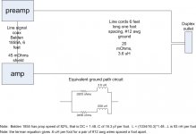
One small correction...it appears that the shield is connected to one of the differential inputs. So the total shield loop resistance will be the sum of the shield R (perhaps 50 milliohms), the contact resistance of the connection (perhaps 10 to 100 milliohms), and the differential input resistance to ground (it looks like several thousand ohms.)
Cheers, John
Last edited:
Thank you.John (jneutron),
I like your reasoning on cable and chassis EMI issues 😉
Regards,
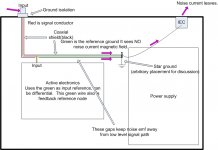
Pics attached..edit..sorry about the pdf, I gotta change that to a jpg..
I believe most of this is self explanatory.
Cheers, John
Attachments
Last edited:
What is important to me is WHY some shielded cables have extra 'distortion' and other shielded cables do not. WHY?
We should also mention not only 'hard' loops. Galvanic ground isolation is a kind of help, but we still have stray capacitances that create loops, currents and induced voltages at higher frequencies. This is still an issue. The setup is usually pretty complex and unique.
What is important to me is WHY some shielded cables have extra 'distortion' and other shielded cables do not. WHY?
They don't. Your test rig does. What I saw when I looked at it was that the distortion was tiny, but repeatable when switching back and forth between cables. This makes contact resistance as your distortion source unlikely. However, the distortion was different than what you had seen the last time you had measured those cables, which is absolutely consistent with the loop hypothesis that jneutron is proposing.
What is important to me is WHY some shielded cables have extra 'distortion' and other shielded cables do not. WHY?
It is understood by your use of quote hashs ( 'distortion' ), that you understand that while it is indeed a difference in measured harmonics, you are now leaving room for it being something other than distortion caused by the cable.
Look at the schematic for the 1700B..specifically, the summing amplifier. Note that the input reference node to the summing opamp is directly connected to ground. Does the test current that made it to the input differential tie directly to the same point at the same location? Is it a star geometry? Is it just a simple trace? Is it a ground plane? Can it alter the performance of the summing amp? Can that current affect any other part of the equipment?
Honestly, I'd punt and install a transformer. However, the exercise of tracing through the current return path provides good input into how one would do this in a power amplifier as well, so the effort is never lost.
Cheers, John
Well, I will stick with what I know, and not with what I am told.
That is perfectly fine.
However, what you now know is that using the ST1700B in the manner you are reporting is not consistent with the design of the equipment. It was not designed to test cables in the fashion you have chosen, so the results are not consistent with reality. Your application points out the flaws in the equipment under such a configuration.
To me, what is more important is that a designer of your high stature and accomplishments not drive down an incorrect path chasing equipment ghosts. Life is too short for us to waste time devoting energy to a dead end such as this.
Your considerable analog expertise would be better used determining the direct source of the harmonics you find, and techniques to correct such bad designs. I have pointed out the path of the current, and that is where the differences you measure are created.
The payback to the analog world you could accomplish in an effort such as that would be huge. It would be a direct application of EMC control strategies to the structure within the analog box, as opposed to the interconnect current control typical of EMC.
It has been, what, 7 years since I first elaborated on this problem to you. I had hoped that you would rise to the occasion, and put into print your efforts. Perhaps another can take the reins and do this...my pics from the earlier post are additional insights and hints that are useful to anyone who chooses to perform this work. If not you...I've given you 7 years to run with it. alas, that was not to be..
Cheers, John
Last edited:
And one might ask:And still, I do not believe you. Sorry.
The question is WHY?
Progress is hard, and even harder if it means abandoning cherished beliefs when the evidence demands it. I can't blame John C too much.
For everyone else, I happen to be designing, at the moment, 2 phono preamps, two power amps, and promoting the Bybee Music Rails to my colleagues. I have enough on my plate. However, if I were to completely ignore this 'problem' and used virtually connecting cable with my test equipment that I might find laying around, I 'might' add higher order distortion to my circuit measurement that is not really there. Then what? After all, the levels that I am running through the wires is consistent with normal measurement. For example, 50mV= 1/4W from my power amp. 50 mV into my phono circuits is 100 times higher than listening levels. IF the cables some way influence the residual on my analyzer, I have to know.
YET, I can avoid this worry by using cables that do NOT show this problem. Problem solved, for the moment. '-)
YET, I can avoid this worry by using cables that do NOT show this problem. Problem solved, for the moment. '-)
And still, I do not believe you. Sorry.
As I said, that is perfectly fine.
I believe it has been at least seven years of you taking these measurements, with nobody else ever being able to repeat your results...
In fact, far better equipment designed for the task finds nothing consistent with what you have reported.
Now, given the public distribution of the design flaws inherent in the equipment used in that test configuration, all can understand why your results are not repeatable. They are ghosts.
But the flaws are a key to designing unbalanced driven amplifiers to be more resistant to ground based loop currents, hum being one aspect.
Cheers, John
- Status
- Not open for further replies.
- Home
- Member Areas
- The Lounge
- John Curl's Blowtorch preamplifier part II