I seed many good reasons to eliminate audio connectors and solder the IC's direct, also with speaker wire.
It explains what i can hear when doing this.
This was done once on a SOTA system with a Krell triamped Apogee Fullrange and you had to be stonedeaf if you could not hear the difference.
I have seen maybe 20 years ago some *pure gold* plated Copper RCA Jacks from WBT, but after a while the gold vanished somehow into the jacks and left a dark black surface with bad conductivity properties and this was audible.
They were used on Goldmund Mimesis Preamps (very high bandwith) and some other gear.
Replaced them and it was fine again.
In all cases where low level effects are being measured, absolute control over all current paths is critical. The AP does this by design. Loss of current path control, vis a vis, non zero net current through a coax, causes susceptibility to external fields. JC also notes his measurements are inundated with TV horiz scan interference from neighbors.
In either the ST or the AP for the tests John is doing the connections are very similar. The inputs in both cases are differential, cables are looped back to the same box in the same ground environment. On the AP you may need to add a ground connection on the differential input to manage the common mode component, which the ST has be default. The only odd ground current will be electrostatic pickup on the shield. The input Z is too high for any EM currents to be significant.
The TV horizontal signal is almost gone, unless you are near someone with a really old TV. With LCD displays and modern TV broadcasts the old problem is history.
I would be even more concerned about contamination on the insulators than the contacts themselves. The high impedances used in this test mean very little current is flowing so it needs very little contact to do the job. However in a noisy space the shielding needs to be good, perhaps a second overall shield around the test fixture.
edit: Within the last half decade, repeated requests on my part for schematic and physical details of the modified 1700 being used by JC after "extensive electronics upgrades" by him have gone unanswered. As have repeated requests for baselining of the equipment to determine the measurement floor and measurement accuracy.
JC reports results of his tests in the -100 to -120db range IIRC, and that requires exquisite attention to current path details. Without such, the results are not necessarily accurate.
Cheers, John
The 1700B John is using now is mine and is box stock. The extensive mods he did to his consist of replacing a few opamps and adjusting it. Not very interesting.
I have not been able to duplicate John's cable distortion measurements so I can't comment.
In either the ST or the AP for the tests John is doing the connections are very similar. The inputs in both cases are differential, cables are looped back to the same box in the same ground environment. On the AP you may need to add a ground connection on the differential input to manage the common mode component, which the ST has be default. The only odd ground current will be electrostatic pickup on the shield. The input Z is too high for any EM currents to be significant.
I noted on page 1-5 the reference to a switch to float the ground of the output, leaving a .001 uf cap. This was to "fix" ground loops. How does this reactance size with respect to 100 db down with a high impedance differential input and the reported harmonics of JC?
I also found in the schematic, the output ground takes the shield all the way back to the summing amplifier, test point S, through the output attenuator. The ground lift switch must do the disconnect from signal ground to IEC ground?
Honestly, If I were to mod that puppy, I'd drop a really good transformer at the output, and completely isolate the output ground from everything. That way, there would be no question of return current isolation.
Unfortunately, that does not mean that the loop pickup mechanism is gone, just the normal source. The fact that the instrument picked up tv horiz means that there was one or more uncontrolled current paths.The TV horizontal signal is almost gone, unless you are near someone with a really old TV. With LCD displays and modern TV broadcasts the old problem is history.
Given JC's reported problems with ground contact resistance, your mention of high impedance lends even more credence to an uncontrolled current path.I would be even more concerned about contamination on the insulators than the contacts themselves. The high impedances used in this test mean very little current is flowing so it needs very little contact to do the job. However in a noisy space the shielding needs to be good, perhaps a second overall shield around the test fixture.
Now I'm confused. JC is reporting tests as of last night..what is he using if you own the 1700B??The 1700B John is using now is mine and is box stock. The extensive mods he did to his consist of replacing a few opamps and adjusting it. Not very interesting.
What an odd thing. I wonder why?I have not been able to duplicate John's cable distortion measurements so I can't comment.
Cheers, John
The 1700B will give an output with too much noise included to NOT use it with a signal averaging following instrument.
Scopes usually have 8-12 bit resolution.
Wrinkle, thank you.
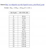
Although my mind was on analogue oscilloscopes, your response made me consider the dynamic range and the expected lowest measurable signal using anything that contains an AD converter (e.g. a sound card).
So I compiled a table (bit depth vs Dynamic Range or SNR).
It seems that with 16bits one can not look lower than -96dB (ref. 0db of card). It takes 20bit to reach -120dB.
George
Attachments
Sure you can. Dither and signal average.
Averaging, yes.
Now dither. Hm, I was under the impression that dithering adds to the noise.
Am I wrong?
I have to read on the subject.
Regards
George
I've had it described to me this way, and it helped me a lot:
The output of an ideal properly bandlimited, properly dithered A/D/A conversion is the original signal, plus a small noise (the dither), plus a time delay. There are no amplitude or timing changes and all signals smaller than the dither are still there. IOW, PFM.
The output of an ideal properly bandlimited, properly dithered A/D/A conversion is the original signal, plus a small noise (the dither), plus a time delay. There are no amplitude or timing changes and all signals smaller than the dither are still there. IOW, PFM.
SY
Before I get lost into the details, may I ask you if the following is correct?
Dither adds to resolution: This is important when I do analysis in the frequency domain (harmonics analysis). But is dithering beneficial also when observing in the time domain?
Averaging: It lowers the (uncorrelated) noise floor. It is beneficial in both frequency domain and time domain analysis.
Thanks in advance.
George
>Edit> Chris, I need some time to digest this !
Last edited:
To worry about the crystal structure in interconnects and "microdiodes, microgaps, whatever" and assign special mystical qualities to such as unmeasurable, yet not comprehend the reality of variable surface conductivity of various heavy gold plating compositions is not seeing the forest for the trees. Pure gold is difficult to obtain, plated from cyanide solutions it contains carbon even when not brightened by a transition metal; plated from sulfite solutions, it contains sulfur at grain boundaries, and arsenic if brightened.
"Heavy" gold plating is, by definition, anything over 2.5 microns or thereabouts. You won't see this very often, other than for research equipment, NASA, military/DOD, etc. Anything under 100 uinch is also porous, hence the need for a diffusion layer (usually nickel, sometimes palladium or something else). And at $1600/oz, you probably won't see much period...
"Heavy" gold plating is, by definition, anything over 2.5 microns or thereabouts. You won't see this very often, other than for research equipment, NASA, military/DOD, etc. Anything under 100 uinch is also porous, hence the need for a diffusion layer (usually nickel, sometimes palladium or something else). And at $1600/oz, you probably won't see much period...
Dither adds to resolution: This is important when I do analysis in the frequency domain (harmonics analysis). But is dithering beneficial also when observing in the time domain?
Depends on what you're trying to observe.
Keep in mind one fundamental thing: ALL of the time domain information is contained in the frequency domain information and vice versa.
Depends on what you're trying to observe.
The beautiful legs of a woman among a crowd of 1000 people. 😀
Keep in mind one fundamental thing: ALL of the time domain information is contained in the frequency domain information and vice versa.
I was expecting that. 😱 I can’t skip the studying.
Auplater
Excellent information and suggestions thereof. 🙂
Regards
George
Last edited:
SY
Before I get lost into the details, may I ask you if the following is correct?
Dither adds to resolution: This is important when I do analysis in the frequency domain (harmonics analysis). But is dithering beneficial also when observing in the time domain?
Averaging: It lowers the (uncorrelated) noise floor. It is beneficial in both frequency domain and time domain analysis.
Thanks in advance.
George
>Edit> Chris, I need some time to digest this !
Thinking about it in a neurological analogy might be helpful to visualize the underlaying process.
Suppose a signal of a sensor, eyes, ears, name it, is burried under the level of detection. By adding noise, the whole signal including this added noise, will be raised above the level of detection. Now, subsequently averaging the signal plus noise that gets over the detection limit will amplify the signal present in that noise more than the noise. It is a trick that has actually been applied in artificial neural networking, but it is also what nature does.
The ear is not silent, nor is the eye a particularly noiseless sensor, as becomes obvious in low dB/Lux environments. And it serves the purpose of pushing a signal over the perception threshold. The averaging out comes next. As we all know, it takes longer for figure out what you are seeing in a dark environment, or whatever you are hearing at low intensity.
I noted on page 1-5 the reference to a switch to float the ground of the output, leaving a .001 uf cap. This was to "fix" ground loops. How does this reactance size with respect to 100 db down with a high impedance differential input and the reported harmonics of JC?
I also found in the schematic, the output ground takes the shield all the way back to the summing amplifier, test point S, through the output attenuator. The ground lift switch must do the disconnect from signal ground to IEC ground?
The ground disconnect switch is for "opening" the potentially shared connection when a scope is connected to the monitor output and there are potential ground loops.
Honestly, If I were to mod that puppy, I'd drop a really good transformer at the output, and completely isolate the output ground from everything. That way, there would be no question of return current isolation.
If the signal never leaves the box except for a cable from the output to the input I don't see how a transformer would make a difference.
Unfortunately, that does not mean that the loop pickup mechanism is gone, just the normal source. The fact that the instrument picked up tv horiz means that there was one or more uncontrolled current paths.
This can be dealt with using a shield enclosure if critical.
Please explain the uncontrolled current path from BNC out to differential input, I may be as dense as depleted uranium so I need help here. All I see is the source and the differential inputs. The shield on the coax is tied to the shield of the BNC and the minus terminal of the differential, the hot to the plus terminal. What is the source of the uncontrolled current?Given JC's reported problems with ground contact resistance, your mention of high impedance lends even more credence to an uncontrolled current path.
A transformer will isolate at DC and have capacitive coupling at AC so Its no panacea. And transformers capable of -120 dB harmonics are hard to find.
He is using it. I use either a Boonton 1121 or Shibasoku (or a Radiometer CLT-1 when I need a low distortion floor).Now I'm confused. JC is reporting tests as of last night..what is he using if you own the 1700B??
What an odd thing. I wonder why?
I have not attempted to duplicate John's cable distortion tests. I have too many other puzzles to pursue.
A posting above may be unintentionally confusing the issue of dither and noise. Dither is composed of noise, but its purpose is *not* simply to make things noisier. Simply adding noise before a measurement helps nothing and detracts from measurement sensitivity.
Dither, on the other hand, is added during the quantization process because it allows signals smaller than the smallest quantization step to be "kept" as information. Without dither smaller signals would be lost. With dither the smaller signals are kept, although they may be below the new noise level. Averaging over longer periods of time favors (repetitive) signal over (random, non-repetitive) noise.
To sum up, dither *makes possible* low signal level measurements, but sometimes at the expense of having to look for a longer time.
Hope this helps some - it's a wonderful subject and a joy to learn about.
- Status
- Not open for further replies.
- Home
- Member Areas
- The Lounge
- John Curl's Blowtorch preamplifier part II