The test board
... and now back to paid development work
Off topic, I'm really surprised, since when is Maxim doing LT1028? There's no trace of that in their catalogue, though your picture seems to show a genuine Maxim part...
Gerard, I don't know how you did it, but you completely missed what we were arguing about. At first I thought you were clarifying the situation, but you didn't put in the IM byproducts in actual contention. You appear to have ignored them.
Please everyone, the two most obvious 'pips' on the graph that really depart from being an IM byproduct are alleged to be: 2F2-8F1, and 2F2-6F1.
They compute to be: 4.56 KHz for 2F2-8F1, and 10.92 KHz for 2F2-6F1.
Do they appear on the actual test (fig 3) to be these frequencies?
Did I do my math wrong?
This is the actual problem.
The questionable frequency pair in high resolution:
Squarewave = 3180 Hz ==> 1380 Hz
Squarewave = 3210 Hz ==> 1110 Hz
IMD product wanders 270 Hz down for input step of 30 Hz
=====> This is IMD with 9 * square wave frequency.
Methinks this argument is settled.
The not so funny thing is that everybody with a tone generator and a soundcard
could have done this in one evening, but nobody did it.
What a breath of fresh air! Nicely done!
Please everyone, the two most obvious 'pips' on the graph that really depart from being an IM byproduct are alleged to be: 2F2-8F1, and 2F2-6F1.
They compute to be: 4.56 KHz for 2F2-8F1, and 10.92 KHz for 2F2-6F1.
Do they appear on the actual test (fig 3) to be these frequencies?
They don't appear to, no.
Even though the peaks in fig. 3 are skewed such that they don't match up with the actual numbers, when 2F2-8F1 and 2F2-6F1 are added to the graph I made previously, their positions are inconsistent with the skewing of the peaks in fig. 3.
When the graph is scaled to match fig. 3 from 0Hz to 15.9kHz, the lower frequency peaks in fig. 3 gradually skew further and further to the left of the peaks of the graph.
However when I add 2F2-8F1 and 2F2-6F1, instead of being to the right of the peaks in fig. 3, they are to the left.
So in spite of the skewing of fig. 3, it's rather evident that the two peaks of interest here are NOT at 2F2-8F1 and 2F2-6F1, but rather are higher in frequency.
Unless of course your math is wrong. 😀
An externally hosted image should be here but it was not working when we last tested it.
se
Last edited:
By the way, when I made the graph, I did so assuming that the leftmost point on the X axis in fig. 3 was 0. I got to thinking that may have not been a good assumption. So I've since scaled the graph between 0.9kHz and 15.9kHz and that gives a near perfect fit and it appears that the leftmost point in fig. 3 is 20Hz.
Now that the graph is properly scaled, I can get a much better estimation of the frequencies of the two peaks in question, and they're at approximately 5kHz and 11.3kHz.
se
Now that the graph is properly scaled, I can get a much better estimation of the frequencies of the two peaks in question, and they're at approximately 5kHz and 11.3kHz.
An externally hosted image should be here but it was not working when we last tested it.
se
Thanks Steve, and if the frequencies don't fit, we have to look elsewhere for the cause. How about FM modulation? 🙄
Thanks Steve, and if the frequencies don't fit, we have to look elsewhere for the cause.
Or as the late Johnnie Cochran might have said, "if the frequencies don't fit, you must acquit." 😀
How about FM modulation? 🙄
I'll let y'all fight over that one. I just wanted to try and get to the bottom of what exactly was represented in fig. 3.
se
That's fair, and I couldn't spell 'acquit' so I left it out.
I did note that the unknown frequencies (at least 4) appear to be symmetrical about the fundamental and the 3'rd harmonic, respectively.
I did note that the unknown frequencies (at least 4) appear to be symmetrical about the fundamental and the 3'rd harmonic, respectively.
Or as the late Johnnie Cochran might have said, "if the frequencies don't fit, you must acquit." 😀
I'll let y'all fight over that one. I just wanted to try and get to the bottom of what exactly was represented in fig. 3.
se
Steve, I had an appointment with Jan Lohstroh today and took the opportunity to go through his files from way back. Came up with this:
http://www.linearaudio.nl/Miscellaneous/espoo 1976.pdf
I haven't gone through it in detail, just scanned and posted it, but it does offer some other perspectives on the DIM method and results.
jd
I did note that the unknown frequencies (at least 4) appear to be symmetrical about the fundamental and the 3'rd harmonic, respectively.
I have to run to the store real quick but I'll get an estimate of the others when I get back.
se
Good try, 11F1-2F2 = 4980. Steve, the square wave would favor the odds.
John, there is no physical mechanism to create non-harmonically related frequencies in this case. You will get yourself in trouble hanging your hat on this.
John, there is no physical mechanism to create non-harmonically related frequencies in this case. You will get yourself in trouble hanging your hat on this.
Last edited:
What to do, however it looks like FM modulation of the square wave, to me. Maybe we should look for the cause.
Hi John,
You must be looking at AM modulation. FM modulation will give you infinite harmonics on either side, reducing in amplitude as you get away from the center frequency. That was my entire point here. http://www.diyaudio.com/forums/showpost.php?p=1916683&postcount=1001
If you AM modulate a single frequency, you then end up with sum, difference and the two original frequencies. It takes special circuitry to create a suppressed carrier or single sideband (either sum or difference).
You need to be clear on what you are looking at before you can even begin to decide what is of significance here.
Now, since there is question as to exact frequencies and amplitudes when referring to the original published graph, it might be time to rerun the experiment again. This would eliminate any ambiguity about what we are looking at. That is why I offered to run the test again, exactly the way as it was done so many years ago. Wouldn't you agree John?
Heed Scott's warning here. Let's figure out what we are looking at.
-Chris
It could be AM distortion, BUT it does not have to be heavily modulated enough to have an extended set of sidebands, so it could still be FM. Darn, I have emulated it on my test bench, at the moment. It looks almost exactly what we have on the graph fig.3.
Steve, I had an appointment with Jan Lohstroh today and took the opportunity to go through his files from way back. Came up with this:
http://www.linearaudio.nl/Miscellaneous/espoo 1976.pdf
I haven't gone through it in detail, just scanned and posted it, but it does offer some other perspectives on the DIM method and results.
jd
Bump.
Hi Jan,
Thank you very much for putting that information up. Right now I'm printing it so I can read it properly. I don't really know how to thank you for searching, scanning and putting that up, I'll assume you had permission. 🙂
Hi gerhard,
Thank you for doing those experiments. Something else to study for sure!
Hi John,
It must be AM modulation. You will get a continuous spectrum with FM modulation. Think about it, you are sweeping the center frequency back and forth in a continuous and repeating way. Your instruments may interpret this differently, but even a practical square wave does not change from one state to another instantly, it has a rise and fall time. So, depending on your instruments and sample rate, it may appear to be AM modulation. In that case, your equipment is not telling the entire story (it's lying to you as I like to say).
To confirm what I'm telling you, replace your square wave source with a sine wave at the same frequency. You should see the classic FM display on your spectrum analyzer.
Now, the test setup posted by gerhard in post 1027, http://www.diyaudio.com/forums/showpost.php?p=1917377&postcount=1027, correct? Will this accurately reproduce what you did originally?
-Chris
Last edited:
Good try, 11F1-2F2 = 4980.
Yeah, my 5.0 wasn't bad for just eyeballing off a jpeg image. And my actual measurement was 4.9 and some change I just rounded it up to 5 even. I wasn't looking at this in terms of intermod frequencies, but simply making relative measurements in inches based on fig. 3.
By the way, here are the approximations of all the unlabeled peaks in fig. 3.
An externally hosted image should be here but it was not working when we last tested it.
se
Chris;
you won't get continuous spectrum with FM. It will be seen similarly to AM since the analyzer shows levels only. If you calculate them mathematically you can get different directions: above zero, and below zero. In case of AM all strips will be above zero. Number of strips you get depends on frequency deviation.
However, when AM and FM modulation present simultaneously heights of strips of different sidebands can be different. When you "sweep" you observe dependence of gain of FM receiver on signal's frequency, no more, so bumps and dips mean non-perfect RF and IF filters.
However, fair modulation and intermodulation will look differently.
Hi Anatoliy,
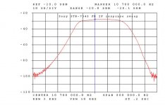
With FM modulation, you get a continuous spectrum. With square wave modulation that is working perfectly, you will get what is called FSK, or frequency shift modulation. The only time you will have a discontinuous spectrum with FM that I know of is if you are sampling in some way. However, the center frequency (or carrier) is changing continuously between the peak high extreme and the peak low extreme of the deviation, or change in frequency. That continuous sweep back and forth "looks" like a continuous spectrum. I'm looking at an FM IF sweep right now, here it is.
Notice that it is continuous in nature. The input is a swept 10.7 MHz center, 800 KHz range. In other words, the high frequency is 10.7 MHz and the low frequency (modulation) is 5 Hz (inverse of sweep time). My earlier post showed 10.7 MHz modulated by 1 KHz, so take your pick from these. I can, and later will, try with the lower frequencies that this thread is concerned with. I don't have time right now and the generator I'm using (HP 8656B) only goes down to 100 KHz. I'll need to use an HP 3324A and 3336B in order to recreate the exact test setup used by John. That is why I have been asking for his test setup - so I can see what he is seeing.
Modulation in a linear analog power amplifier will be AM for the most part, FM modulation is what I think they are looking for, and may occur at very low modulation depths. Can you imagine listening to an amplifier that is being modulated using FM? That might be somewhat like listening to a turntable suffering from wow and or flutter. A frequency effect hard to miss.
Best, Chris
Attachments
Last edited:
- Status
- Not open for further replies.
- Home
- Member Areas
- The Lounge
- John Curl's Blowtorch preamplifier part II