Richard,
That is so true in many industries. I'm seeing that now with some high speed composites development, they are just now catching up to some things I did over 20 years ago with Bayer Material Science, stuff we never published and now I couldn't give away, they have to reinvent it themselves. They are trying to get under a five minute cycle time and we were doing it in 90 seconds twenty years ago.
That is so true in many industries. I'm seeing that now with some high speed composites development, they are just now catching up to some things I did over 20 years ago with Bayer Material Science, stuff we never published and now I couldn't give away, they have to reinvent it themselves. They are trying to get under a five minute cycle time and we were doing it in 90 seconds twenty years ago.
Same with old school analogue electronics engineers, they (like real PCB designers) are becoming an endangered species... On one project (analogue and audio) the new generation spent two years messing about, when passed on to a real analogue engineer all sorted out in 4 months....
Then the management decided to go digital (because it is fashionable and a quick change of software is all that's needed to upgrade and improve the product!!!) and DSP, just add a pile of DSP programmers at silly amounts an hour, still working on the software 2 more years down the line....
For learning about EMC though you cant beat real RF engineers.
In as large print than your lack of courtesy ?...you are unfamiliar with the well known fact ...
...your inability to recognize and react properly to a clear presentation of correct technology is noted.
Well I got my desk cleaned today so a bit of play.
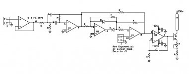
I am looking at building a 1/3 octave display using nixie style bar graphs. These go up and down depending on the drive current. So a variable voltage into a transistor base with an emitter resistor should do as a current converter. calibration is adjusting that resistor value. This is driven by a low pass filtered comparator that is feed with the DC value of the filtered signal after rectification and either a linear ramp voltage or a nice exponential ramp for a dB style readout.
Basic schematic is attached.
Attachments
Ed, good to see you back! I thought that you might tell everybody your opinion why the 4562 does rectify and the 797 doesn't.
Ed, good to see you back! I thought that you might tell everybody your opinion why the 4562 does rectify and the 797 doesn't.
Long long ago in this thread or even the first version the issue was raised and the best explanation was that the input stage is running at too low a current level.
The LM draws 5 mA per amplifier, the AD a bit more than 8 typical. How much more current for the input pair is probably a secret.
I am looking at building a 1/3 octave display using nixie style bar graphs.
Something like that?
Audio Vu meter with IN13 or IN9 Russian nixie bargraph tubes
https://www.youtube.com/watch?v=NqsuAlrJUOc
Last edited:
Did the designer survive?
Demian, I wonder if he (or she) survived in the acquisition of National by TI?I gather it is a very highly tweaked linear process. The designer was a wizard they brought in from Japan.
There are probably a number of technologies that have been lost. A specific and important one is the metallurgy for the ultrastable resistors. The alloy and process for making it apparently have been lost so the existing supply is all there is. I gather the issue is that the guys who figured it out retired/died and the details were lost. It seems this happens with low priority products regardless of their real importance.
My understanding is that TI is shutting down the National line the LME parts were made on so they are all destined to be discontinued. Apparently TI does not have a place they can move it to. I gather it is a very highly tweaked linear process. The designer was a wizard they brought in from Japan.
It would be interesting to see if the LME49990 has the same "sensitivity" as the LME49710.
These stories are possibly folklore, they sound romantic and all that but I would take them with a grain of salt. the metallurgy for ultra stable thin film resistors is well known and in no danger of being lost.
The SMD and metal can versions are available on Mouser. I think its just the PDIP that are discontinued. As I remarked a few posts back, we will see more and more of these larger packages (i.e. leaded) go by the wayside. Its cheaper to make SMD parts and that's where the volume it. If you make specialist parts for specialist customers and can charge a lot of money for them, then there may be a case for keeping leaded parts. SMD is the future whether we like it of not.
Of course, if its about closing down a line and it's going to cost more to move the process to a newer line, then often a decision to kill the product family has to be made - its a straight $ and cents thing.
(BC547/BC557 TO-92 recently discontinued as well . . . .)
Of course, if its about closing down a line and it's going to cost more to move the process to a newer line, then often a decision to kill the product family has to be made - its a straight $ and cents thing.
(BC547/BC557 TO-92 recently discontinued as well . . . .)
Last edited:
I think Hofer and others are now saying that thin film SM resistors are virtually perfect for most purposes, which is fine by me except for the stalwarts turning up their noses when they see surface mount on the board. And of course they are less friendly parts for breadboarding.These stories are possibly folklore, they sound romantic and all that but I would take them with a grain of salt. the metallurgy for ultra stable thin film resistors is well known and in no danger of being lost.
I have a friend who told me that he was using some exotic, was it tantalum? leaded part for a grid snubber. I have learned to be nice about such things.
More just the footprint of the final product, customers are pushing back big time on package height/size on smart/fitness watches for instance.Its cheaper to make SMD parts and that's where the volume is.
metal can versions are available
Mr Russell,
odd question, but would it be feasible to xray the die and thermal image it (flip t430) ?
These stories are possibly folklore, they sound romantic and all that but I would take them with a grain of salt. the metallurgy for ultra stable thin film resistors is well known and in no danger of being lost.
Its not thin film but wirewound resistors using evenohm or similar for standards applications. I got it from the remaining manufacturer of those resistors: 200 Series - 0.1 ohm to Ten Megohms | Ohm-Labs, Inc.. Of course he may have been selling me a bill of goods. NIST has moved to Josephson Junctions for resistance standards but still has wirewound standards using evenohm or manganin wire. Here is some interesting history: http://www.nist.gov/calibrations/upload/87mscohm.pdf
And the story about TI/National came from a product manager for the LME products (who is unemployed now like a lot of the National guys). But it matches the list of discontinued products and is consistent with TI's process taking over companies.
The SMD and metal can versions are available on Mouser. I think its just the PDIP that are discontinued. As I remarked a few posts back, we will see more and more of these larger packages (i.e. leaded) go by the wayside. Its cheaper to make SMD parts and that's where the volume it. If you make specialist parts for specialist customers and can charge a lot of money for them, then there may be a case for keeping leaded parts. SMD is the future whether we like it of not.
Of course, if its about closing down a line and it's going to cost more to move the process to a newer line, then often a decision to kill the product family has to be made - its a straight $ and cents thing.
(BC547/BC557 TO-92 recently discontinued as well . . . .)
Commercial designs these days use very few PTH parts, I work now in a bureau with 5 permanent and 4 contract PCB designers, apart from the space stuff and some pro-audio (guitar amps etc) we very rarely see a through hole component that is not a connector (and even these were possible are going to SMD).
The advantage with SMD though is size I would have thought for low level analogue (I do a lot of analogue layouts, mostly control and instrumentation, std SOIC 1.27 pitch are often used) smaller loop areas for one and as such better immunity to airborne EMI or internal EMI, better thermal control, the caveat is its harder for DIYers to assemble. You can also do high power using SMD, though often magnetics and large caps have to be PTH.
Mr Russell,
odd question, but would it be feasible to xray the die and thermal image it (flip t430) ?
Sorry Jacco, unfortunately I am not qualified to answer that - I would not know.
As an aside, we did thermally image power die with built in thermal shutdown. I was very surprised to find the current limit>thermal overload> cycle time was 1kHz - i.e. very fast.
Commercial designs these days use very few PTH parts, I work now in a bureau with 5 permanent and 4 contract PCB designers, apart from the space stuff and some pro-audio (guitar amps etc) we very rarely see a through hole component that is not a connector (and even these were possible are going to SMD).
The advantage with SMD though is size I would have thought for low level analogue (I do a lot of analogue layouts, mostly control and instrumentation, std SOIC 1.27 pitch are often used) smaller loop areas for one and as such better immunity to airborne EMI or internal EMI, better thermal control, the caveat is its harder for DIYers to assemble. You can also do high power using SMD, though often magnetics and large caps have to be PTH.
Agree - there are a lot of benefits to going SMD and better EMI performance is one along with the smaller PCB and product real estate Scott mentioned. I just put down a 28 pin microcontroller with a 0.5mm lead pitch on my PCB by hand and it went down fine and looks good. So, SMD is not the horror DIY'ers think it is. SOT23, 1206, 0805 and 0603, 0.5 mm pitch IC's and similar size components are all easy to place - you need a very fine tipped soldering iron, fine tipped tweezers and 0.8 or 0.6mm diameter solder. I use reading glasses and also have one of those magnifying glass things you put on your head. If you are trying put these devices down using a conventional iron tip you are not going to be successful.
By the way, at my former employer we made 70 billion discrete SMD devices a year (70 x 10^9) - no way you can do that kind of volume with leaded devices.
I'm not surprised, the figures for discrete placed per day is in the billions I believe worldwide, cant find the IPC report to confirm the figure, but it is staggering.
I do a few designs with 0201s and the silly devices (0.5 and 0.4mm BGA's and QFNs) all via in PAD HDI layouts... fun🙂
I do a few designs with 0201s and the silly devices (0.5 and 0.4mm BGA's and QFNs) all via in PAD HDI layouts... fun🙂
Correction - the IC I just placed has a lead pitch of 1.27mm center to center. I am not quite good enough to place 0.5mm c2c devices yet.
😉
😉
I'm not surprised, the figures for discrete placed per day is in the billions I believe worldwide, cant find the IPC report to confirm the figure, but it is staggering.
I do a few designs with 0201s and the silly devices (0.5 and 0.4mm BGA's and QFNs) all via in PAD HDI layouts... fun🙂
The volumes are indeed huge - I always wondered where the hell it all went. The average TV has 100+ of these devices - so that's >2 billion annually. A phone has about 20- that's 20 billion there, tablets have 20 or so . . . it all quickly adds up.
- Status
- Not open for further replies.
- Home
- Member Areas
- The Lounge
- John Curl's Blowtorch preamplifier part II