No real current drive tried yet, 6.8ohm is still far from current drive and is comparable to speaker impedance. From my measurements it seems that DF does not change distortion much, almost negligibly. Fair to say that higher DF means more flat frequency response.
I think it is obvious that some speakers benefit from current drive and some don't, for any given frequency. To state flatly that one is better is weirdly divisive.
Agreed, so far.
This is all you need to do to significantly reduce driver output distortion; Any high nfb (VFB) power amp can be modified easily for this configuration and tested with your own speaker of choice (I published this decades ago):
An Rs of .2-.5 works well.
View attachment 460864
THx-RNMarsh
Hot dang, Richard, I wish I had read your papers on the matter BEFORE I did my speakers. I arrived at almost the same point by simple trial and error - tried 0.22, 0.27, 0.33, 0.39, 0.47, 0.56 Ohms and found that 0.33 Ohms worked best across the board. It simply cleaned up the speaker, made it more detailed and coherent. Not like a revolution, but enough to be clearly audible with vs. without.
Last edited:
So, two days later, no-one knows and/or cares whether the amp's damping factor has anything to do with this, and if it does to what extent?
Damping factor is based on the idea that the ideal speaker source has zero impedance. This is pretty dubious because any SS amplifier will have far less impedance than the speaker already.
The way to increase damping factor is to decrease the output impedance. But for everything but tube designs, the output impedance is less than 1% of the speaker impedance. So now instead of having 8R resistance in series with the coil, you now have 8.08R resistance. This amount of change cannot do anything on the level of current drive or negative resistance drive.
My question would be what physically would be changed in a speaker to make it either a voltage or current driven device? What exactly would change in the motor or voicecoil design, I am at a loss where the difference would be.
No real current drive tried yet, 6.8ohm is still far from current drive and is comparable to speaker impedance. From my measurements it seems that DF does not change distortion much, almost negligibly. Fair to say that higher DF means more flat frequency response.
Well, that's not easy to ignore, is it?
I measure with Zout = 0.23 ohm amplifier, no GNFB. + speaker cable.
Amp distortion into resistive load 4 - 8R < 0.001%
Complex load reflects a proportional ratio to 0.23 ohm. Soundcard measurements reliable > 0.004%. Still enough for these speaker measurements.
Amp distortion into resistive load 4 - 8R < 0.001%
Complex load reflects a proportional ratio to 0.23 ohm. Soundcard measurements reliable > 0.004%. Still enough for these speaker measurements.
From what I am gathering it seems that the impedance of the device is one of the only changes that you could change to do make a speaker a current driven device? Is that what I am reading here? How would you do that. thinner wire to increase the inherent resistance or a more windings increasing the resistance. Both of those solutions would have other effects. thinner wire would not handle the current very well and a long voicecoil wire would add a large mass to the moving mass and change everything else in the speaker design to counter the increased mass. So what is the proposal to make a speaker for current drive?
From what I am gathering it seems that the impedance of the device is one of the only changes that you could change to do make a speaker a current driven device? Is that what I am reading here? How would you do that. thinner wire to increase the inherent resistance or a more windings increasing the resistance. Both of those solutions would have other effects. thinner wire would not handle the current very well and a long voicecoil wire would add a large mass to the moving mass and change everything else in the speaker design to counter the increased mass. So what is the proposal to make a speaker for current drive?
An amplifier can be voltage drive or current drive. In current drive mode the amp output current does not respond to output voltage (definition of high impedance), and the amplifier output is current rather than voltage. This means that the same way output current for a voltage drive amp depends only on load impedance, output voltage for a current drive amp depends only on load impedance.
Yeah that wasn't it, this was the one or one like it back then.
This uses current feedback, not an accelerometer and a variation of a much older dc motor control technique for improving speed regulation.
Motional feed back amplifier - Electronic Circuits and Diagram-Electronics Projects and Design[/url
Tom
The German link says about the Panasonic loudspeaker that the feedback is of the electrodynamic type (I read it as a secondary coil) but I can’t find the schematic to confirm. This would make it a genuine MFB
How many here have heard the Philips Motional Feedback speaker models in real life? As either Philips or Grundig?
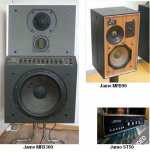
I have experience with the Philips MFB bass drivers installed into Jamo MFB90 and MFB300 active loudspeakers.
I have only good words to say in terms of good sound.
Where I was working at the time for three years, these two sets of speakers made the difference as we had zero calls for malfunctioning or burn.
Considering the installations (apart from selected home users) were at music halls, conference rooms, clubs and discotheques, this was quite a fist and a proof of proper functioning of the MFB concept.
Single speaker sets as well as arrays of speakers ( I remember up to twenty per channel) were driven by the Jamo ST50 preamplifier.
They are not strictly acoustic suspension anymore. The foam surround (among other things) was meant to provide a controlled air leak. But I wouldn’t mind either. I hate to see the surrounds disintegrate.While I honestly cannot swear that the speakers are now as new, any difference between as new and with new suspensions I can vouch for the fact that any differences are small enough not to be easily detectable.
Exactly, at acoustical side it looks quite opposite..The same speaker, voltage driven and through series resistor, to the same SPL
I think that something went seriously wrong there.
Almost half the power is dissipated at the added series resistance. If you increased the volume for to get equal acoustic spl as with the no series resistance case, the amplifier might have overloaded or couldn’t provide that power to the load.
Did you check the waveform with an oscilloscope at the amplifier output?
These systems are all mounted in the scoreboard, have a listen
Tom I had a listen and I am impressed. Hats off to you.
Now you reboosted my desire to clone a Synergy Horn for home use
George
Attachments
Last edited:
[...] or maybe all this THD stuff doesn't amount to much.
Indeed. How much of it do we hear?
Auditory Perception of Nonlinear Distortion
- Theory
Earl R. Geddes1 and Lidia W. Lee2
http://www.gedlee.com/downloads/Distortion_AES_I.pdf
The following has the experimental data:
Auditory Perception of Nonlinear Distortion
Lidia W. Lee1 and Earl R. Geddes2
http://www.gedlee.com/downloads/Distortion_AES_II.pdf
Subjective Testing of Compression Drivers
Earl R. Geddes, GedLee LLC, Northville, MI 48167
Lidia W. Lee, Eastern Michigan University, Ypsilanti, MI 48197
and
Roberto Magalotti, B&C Speakers, Florence, Italy
http://www.gedlee.com/downloads/AES_subjective.pdf
Website
Perception
So, two days later, no-one knows and/or cares whether the amp's damping factor has anything to do with this, and if it does to what extent?
Richard spoke of "high NFB" amp, which begs the question - what about low NFB amps, which use 26 dB or less of GNFB? How are they affected, more or less, and if as I suspect less, how much less, significantly or marginally?
In practical terms once the DF is in the range of about 20-40, the response shape of the woofer stops changing and there is no further improvement with higher DF's although the numbers look good .
Using current feedback to produce a negative impedance is a step beyond normal electrodynamic damping.
Try it at lower SPL (increase microphone distance).. What about microphone distortion?
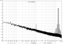
I did, almost no difference. As a microphone check, I have already shown a measurement of 13+14kHz CCIF IMD.
2 methods of signal generation:
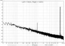
1) Left speaker = 13kHz, Right speaker 14kHz. In the microphone measurement, you see only 2nd harmonic (difference tone). No skirts around 13 and 14kHz, no odd harmonics.
2) 13+14kHz signal only from left speaker. Immediately you can see skirts - odd harmonics up to 9th, product of the speaker.
Attachments
Indeed. How much of it do we hear?
My take is that not enough has been known, yet, on this topic.

The white stuff is a single wire folded and twisted. This decreases the inductance of the length of wire, and also make it's field couple less out external fields. I suspect it is being used as a resistor, small value inductor, or both. I can't see what the other end is hooked up to.
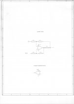
This is all you need to do to significantly reduce driver output distortion; Any high nfb (VFB) power amp can be modified easily for this configuration and tested with your own speaker of choice (I published this decades ago):
An Rs of .2-.5 works well.
View attachment 460864
This looks like the circuits designed to create a higher output impedance.
If Rf is very large, it will mostly be a current source.
Let's try a thought experiment. Assume that a positive applied to the
speaker (+) results in the cone pushing out.
The back emf of the cone moving outward is electrically positive, which is
why the impedance is increased in motion.
If I simply pull the cone outward, then a positive back emf appears at the +
speaker terminal. Think of it as distortion, since the amplifier is not asking
the speaker to perform this motion.
If the + input of the amplifier is held to ground, then this appears as a minus
across the 0.2 ohms, and if this is fed to the - input of the amplifier then it
would appear as a positive at the output of the amplifier. This does nothing
to counter the force pulling the the cone out, rather the opposite.
Are you sure you wouldn't rather invert the polarity of the feedback from
the speaker?
😎
- Status
- Not open for further replies.
- Home
- Member Areas
- The Lounge
- John Curl's Blowtorch preamplifier part II