Hypex sell several SMPS as well as their Class D N'core.
The measurements your referred were for Their Class D AMPs, i suppose ? Not their SMPS ?
I see no 450 KHz in their SMPS. And, by definition, they are loaded capacitively ;-)
The problem is most of them are regulated.
I have measured their their Hypex NC400 amplifier. At least my measurement is independent 🙂
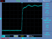
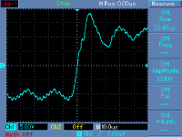
THD is vanishingly low, but it is not everything. I do not like behavior of class D amps. Attached is step response into 10 ohm and 10 ohm//6.8uF. I do not care what manufacturers claim, this is real and repeated on 2 pieces.
P.S.: to measure THD, I have built a passive, 2 x RC filter with 20kHz cut off to get rid of the HF and middle freq mess.
Attachments

Last edited:
Interesting that it oscillates into a such a large capacitor! This is evidence of a multi-order feedback loop being used to increase the feedback bandwidth. If you can tolerate resonances in clever places, then maybe you could do even better. Maybe this is the case with the class D amps?
Any amplifier would be expected to resonate into a 6.8uF capacitor, but if it rings even without a capacitive load, I wonder what kind of output snubber would be required to critically damp it?
Any amplifier would be expected to resonate into a 6.8uF capacitor, but if it rings even without a capacitive load, I wonder what kind of output snubber would be required to critically damp it?
PMA gave me the conformation for what I also saw.
Pavel probed the output of a class D amplifier:
So what you've seen there is not what you were referring to (SMPS)
George
I am concerned with 'out of band' frequencies that are so strong that they interfere with measurement. The Hypex devices that we put into this amplifier are used as a variable tracking power supply. They are the source of the ultrasonic garbage.
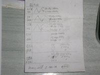
Here is what the output of a Meanwell S-240-24 MW02 (24V/10A SMPS) looks like on an 20MHz oscilloscope when I probed it years ago .
First column is current (A) into load (R).
Second column is main ripple at 100kHz with a fairly constant amplitude and 5MHz glitches which increase in amplitude with load current.
George
First column is current (A) into load (R).
Second column is main ripple at 100kHz with a fairly constant amplitude and 5MHz glitches which increase in amplitude with load current.
George
Attachments
my favorite trick 🙂
never netted me any REALLY good stuff , though ...
mlloyd1
never netted me any REALLY good stuff , though ...
mlloyd1
Yes, I saved it from the bin, along with a few other things. The trick is you stash them in your office and see if they get on the gone missing/needs cal list.
The top one AP High Performance Audio Analyzer & Audio Test Instruments : Accessories
An excellent experimental setup, thanks for the info, jn - down the track I may be tempted to try something similar, 😉.As I earlier stated, by twisting with the far end locked, the conductors will be twisted as well as the bundle. By allowing the ends to be loose, the conductors will not internally twist. The distinction becomes apparent when tension is released, as the bound end pair will loosen up, allowing the conductor spacing to increase whereas the free end one will remain tighter.
About ten years ago, I made a twist fixture for 4 #12 awg wires, it had 4 independently rotatable spool holders on a larger diameter platform. I had the option of locking the spools to the platform, rotating them at the opposite rate as the platform to eliminate conductor twist, and rotating them faster in the opposite direction, which forced the conductors to be twisted but in a way that the conductor trying to untwist forced the bundle tighter..
Here's a picture of it early into the build. Don't know where the final pics are..🙁.
For a start, I would be curious if the description and explanation for the processing of the cable has merit - those with experience in metallurgy should be able to shed some light on this ...You are correct the wrong thread......
How does a signal propagate down a cable? electrons travel very slowly when this is happening 0.1mm/s or so, bumping in to everything in their way, would a few micro cracks affect them, nope, would the micro cracks affect the TEM wave, nope.
Yes, I saved it from the bin, along with a few other things. The trick is you stash them in your office and see if they get on the gone missing/needs cal list.
The top one AP High Performance Audio Analyzer & Audio Test Instruments : Accessories
This has a more reasonable price: AES17 1998 Switching Amplifier Lowpass Low Pass Filter | eBay
Somewhere I reverse engineered the AP box but I can't find it right now. That box is completely passive and the inductors appear to be very carefully worked out for it. I will find the disk I stored it on but it may take a while.
As I earlier stated, by twisting with the far end locked, the conductors will be twisted as well as the bundle. By allowing the ends to be loose, the conductors will not internally twist. The distinction becomes apparent when tension is released, as the bound end pair will loosen up, allowing the conductor spacing to increase whereas the free end one will remain tighter.
About ten years ago, I made a twist fixture for 4 #12 awg wires, it had 4 independently rotatable spool holders on a larger diameter platform. I had the option of locking the spools to the platform, rotating them at the opposite rate as the platform to eliminate conductor twist, and rotating them faster in the opposite direction, which forced the conductors to be twisted but in a way that the conductor trying to untwist forced the bundle tighter..
Here's a picture of it early into the build. Don't know where the final pics are..🙁
jn
Looks like a homebrew planetary strander. Here is a commercial example in operation: https://www.youtube.com/watch?v=0idgUXooAVo The ones I have seen usually have way more carriages and spools but are for smaller wires. usually you want a planetary stranding so the wire is more flexible and less prone to breaking under flex. Here is a pretty good primer on making wire I ran across: http://www.siongboon.com/projects/2007-12-22_cable_wiring/A Guide to Wire and Cable Construction.pdf .
More fun to watch is a braiding machine. Designing one of those is not a simple linear process. https://www.youtube.com/watch?v=OtCrmQvGpjY
Pavel probed the output of a class D amplifier:
So what you've seen there is not what you were referring to (SMPS)
George
Yes, I have never referred to SMPS alone. I have spoken about Hypex class D PWM amplifier.
Very interesting. I've discovered a new phrase, "variable backtwist", which introduces yet another factor which may or may not have significance ...Looks like a homebrew planetary strander. https://www.youtube.com/watch?v=OtCrmQvGpjY
An excellent experimental setup, thanks for the info, jn - down the track I may be tempted to try something similar, 😉.
The structure is built using lazy susan bearings. 6 inchers for the spools, a 12 incher for the platform.
Oh, btw. the round platform is what I was routing out of a 2 by 4 mdf sheet supported at each end with sawhorses. Just as I was completing the cut using a homebrew circle router adapter, the sheet broke, sending router to the pavement. Twas exactly like wiley coyote in a road runner cartoon..luckily the router bit didn't land on my foot. An inch of mdf at the two edges wasn't sufficient to support the work.
Thanks for the links. At the time, I was running a pair of 90 foot 12 awg speaker cables, and needed a single cable run to replace it. And flexible it was NOT.Looks like a homebrew planetary strander. Here is a commercial example in operation: https://www.youtube.com/watch?v=0idgUXooAVo The ones I have seen usually have way more carriages and spools but are for smaller wires. usually you want a planetary stranding so the wire is more flexible and less prone to breaking under flex. Here is a pretty good primer on making wire I ran across: http://www.siongboon.com/projects/2007-12-22_cable_wiring/A Guide to Wire and Cable Construction.pdf .
More fun to watch is a braiding machine. Designing one of those is not a simple linear process. https://www.youtube.com/watch?v=OtCrmQvGpjY
I started designing a braiding machine to handle 8 and 16 strands of smaller gauge, but once I learned enough to understand how to make one, decided that the chance of me living another hundred years was shall we say, fleeting?
Very interesting. I've discovered a new phrase, "variable backtwist", which introduces yet another factor which may or may not have significance ...
I love all these new terms...
jn
Re: the drill chuck method, I find that for single strand wires, twisting up too tight and then reversing the drill to untwist a little yields a twisted pair that is stable and does not self unwind.
Dan.
Dan.
Say Say Say by Paul McCartney and Michael Jackson - YouTubeVery interesting. I've discovered a new phrase, "variable backtwist", which introduces yet another factor which may or may not have significance ...
To answer a few previous questions on switching power supplies: I had a problem that appeared to be the main analog amp that is in my hi fi playback. I decided to test it on the bench, which still has the HP339 hooked up, ready to go. After finding that my analog amp was OK, I then tested an experimental hybrid power amp that I have in my lab, and this is where I saw the high frequency tone riding on the main tone. The analog power amp is absolutely 'quiet' in this sense, and this hybrid power amp ONLY uses the Hypex Class D amps as a tracking power supply, it is NOT, strictly speaking, a Class D amp. I was surprised and disappointed when the residual RF (anything 50KHz and above is RFI to me) was so high that it interfered with a simple harmonic distortion measurement, even with a 3 pole 30KH filter in the HP339 switched in.
Just think what many amateurs here are going to find, when they 'enthusiastically' start playing with switching power supplies? This was the point of my original comment.
Just think what many amateurs here are going to find, when they 'enthusiastically' start playing with switching power supplies? This was the point of my original comment.
To answer a few previous questions on switching power supplies
…
Just think what many amateurs here are going to find, when they 'enthusiastically' start playing with switching power supplies? This was the point of my original comment.
This site stubbornly insist supporting the idea of diy and amateurism, and there are many of it's members who fight with their own devils (taboos).
You should explain in detail what is this experimental hybrid power amp and furnish some measurements if you want to use this example as a vehicle for meaningful technical discussion about SMPS.
George
Go for it, Gpapag. If ONLY everyone was as sophisticated in circuit design as you are, then I would not have to post a warning.
For everyone else, stick with linear supplies, if possible.
For everyone else, stick with linear supplies, if possible.
Re: the drill chuck method, I find that for single strand wires, twisting up too tight and then reversing the drill to untwist a little yields a twisted pair that is stable and does not self unwind.
Dan.
I spin the wire using the drill, and before disconnecting, give the wire length a good pull, that helps set the twist a bit. Then, disconnect but hold the wire from spinning when cut, let it unspin gently.
Leaving the far end unclamped doesn't "kick back" at you.
jn
- Status
- Not open for further replies.
- Home
- Member Areas
- The Lounge
- John Curl's Blowtorch preamplifier part II