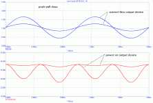
OK, I made a brief simulation on push-pull class A dissipation. I used some real circuit to make it quick. This is a primary school of power amplifiers. Power (red) is for 2 different output amplitudes. Blue is a current (idle of some 1.6A) thru one output device for two different output voltage amplitudes.
Attachments
Pavel, it is valid for a push-pull stage biased in class A, but not valid for a stage designed for class A, like in my Tower amps.
As soon as I designed it and proved the concept, the rule of thumb is no more valid. It is not a problem anymore, at least it is not unavoidable problem.
As soon as I designed it and proved the concept, the rule of thumb is no more valid. It is not a problem anymore, at least it is not unavoidable problem.
Chris:
You're making a good point, often overlooked by engineers.
The effect of this issue, is often causing issues in both electrical and mechanical engineering.
One of the main reasons that the "calculations is the only way" attitude seems to cause problems, is that often tolerances are not taken into account in the equation, as it would make the equation quite complex.
Safety factors are relatively easy to feed into an equation, but when you have a tolerance in both ends of the scale, so to speak, it's all of a sudden a quite different ballgame.
I see the result of this quite often in my everyday job.
Either tolerances were not summed up, or over engineering, making the final device malfunction.
So much for simplified equations.
Magura 🙂
PMA said:OK, I made a brief simulation on push-pull class A dissipation. I used some real circuit to make it quick. This is a primary school of power amplifiers. Power (red) is for 2 different output amplitudes. Blue is a current (idle of some 1.6A) thru one output device for two different output voltage amplitudes.
Nice to see the freq doubling confirmed 😉
Quiz: what is the relationship between load resistance, bias current and supply voltage to make the dissipation curve linear? Is there such a condition? Hint: if Iout doubles, but Vce halves, dissipation remains constant.
(A simplified equation will do). Any engineers out there?
I'd do it myself but I need to go to a Masterclass Tube Design 😀. Really!
jd
janneman said:
Nice to see the freq doubling confirmed 😉
Quite difficult task to force the power to get negative 😀
I noted by
http://www.diyaudio.com/forums/showthread.php?s=&threadid=71189&perpage=25&pagenumber=15
that many "death links" are to find, e. g. from Richard Perez (Justcallmedad). Also about http://www.archive.org/web/web.php I don't get this one.
http://www.diyaudio.com/forums/showthread.php?s=&threadid=71189&perpage=25&pagenumber=15
that many "death links" are to find, e. g. from Richard Perez (Justcallmedad). Also about http://www.archive.org/web/web.php I don't get this one.
Don't worry S; in your new amp output devices will have always the same temperature. However, they will be heated by another devices that bootstrap them and provide current compensation, but time constant of such heating will be huge due to mass and size of a heatsink.
FWIW, in various appnotes (eg from Apex) I find Stinius' equations... so that's seems to be right.
In the Apex AN01 there are some equations for reactive loads, extending the one for the resistive case.
--------:---------
@Jan: I think there is no way to get constant power with real world complex loads and EF's/SF's unless one uses cascodes which generate an (approximated) optimum load line for the instanteous current, regardless of voltage (as they aren't corelated).
Other way would be not to use plain EF's/SF's, then...
- Klaus
KSTR said:
Other way would be not to use plain EF's/SF's, then...
It's exactly what I am talking about.
It is very easy (so I do not know why we need it), but do not forget that an idle current and supply rails are parameters. Not enough to say class AB.
john curl said:Equations look good, so far.
The equations are good
KSTR said:FWIW, in various appnotes (eg from Apex) I find Stinius' equations... so that's seems to be right.
In the Apex AN01 there are some equations for reactive loads, extending the one for the resistive case.
- Klaus
Right
john curl said:We need a class A-B 1 and A-B 2 model, B is not what a SOTA amp uses.
You can use the same model, just adjust it.
Cheers
- Status
- Not open for further replies.
- Home
- Member Areas
- The Lounge
- John Curl's Blowtorch preamplifier part II
