I assumed the second part of the second sentence was your explanation, not his. Maybe the comma sent me off on the wrong path? However, you appear to agree with him - or are you quoting him out of puzzlement and disagreement?jneutron said:This is the scope photo. He states this is the reflection of a 10 Khz signal, so that makes the reflection 4 microseconds.
I assumed the second part of the second sentence was your explanation, not his. Maybe the comma sent me off on the wrong path? However, you appear to agree with him - or are you quoting him out of puzzlement and disagreement?
I quoted verbatim what he said. He marked and texted the word "delay" on the picture, I merely counted those itty bitty hash marks across the center line, understood the full screen to be 100 microseconds (10 KHz), and put a number to what he labeled "delay".
Cyril has measured and reported a reflection that occurs "4 uSec" delayed with respect to the stimulus.
His explanation is consistent with a short t-line mis-terminated at both ends.
Do you have the article?
jn
To quote a wise sage...Condemnation without understanding is prejudice.Audio band reflections of <20kHz waves on 2m of speaker cable are either unimportant or nonsense and rather both.
jn
Although I have not the equipment to venture into this area, my experiences would suggest this is right on the money ...The important thing are reflections at high frequencies (HF interference) and its influence on power amplifier audio band properties. I have done my first measurements of this phenomenon more than 10 years ago. AFAIK NP had published an article on similar theme even earlier.
I have found that this 'series' of loudspeakers from the WATT1 to the Sasha works for me to reveal the subtle details that make differences in audio electronics most easily audible.
Another way is direct driven electrostatic microphones, which I also sometimes use.
An excellent counter-example is the Sequerra Met7. I got them cheap! And I have used them 10 times more than the WATT's over the years. They do OK, but they are 'forgiving' and that makes them difficult to use for serious evaluation of other components.
Without acoustic reproduces of similar quality to the WATT's or the STAX headphones, I can understand why many here don't bother much with subtle differences in audio electronics.
Hope you didn't get the green ones John ........ 😛
Attachments

Horn...ey
I recall building a slew of folded horns from 3/4" ply between 1968 and 1973 , in college, back in Charlottesville, for innumerable fraternity brothers. Great for massive dance (smoke,etc.) parties, highly efficient with the Kenwood, Marantz, Ampzilla,Fisher, Allied etc. amps at the time....
cheap 3 to 6 ft^3 enclosures with EV SP8B's... SP12's JBL LE12's etc. available at the time. Low power... HIGH output!!!
Ohh for the nostalgia.... eh? No worries about healthcare, wives, etc.....
John L.
I used my mono AR-1 based system from 1963-1967, in several locations, fairly successfully. Certainly it was better than most other 'student' systems, and I continued to experiment, with phono cartridges and adding a 'tweeter' to the AR-1. I finished college and got my first professional job(s), one in a hi end audio store that specialized in K-horns, triode amps, Mac, and Ortofon, etc., and my first professional job in electronics design (Friden) working under very experienced electronic engineers. I first heard and compared the AR to a K-horn in 1965. Wow! The K-horn just blew it out of the water. I promised myself that in future, I would get a K-horn or two when I could afford them. I also was able to compare the sound of the Ortofon moving coil cartridge with the latest Shure, etc cartridges, and again the Ortofon won hands-down.
So I switched my focus from AR to Paul Klipsch, as far as ultimate speaker quality was concerned, and I even met with and talked to Paul Klipsch, himself on several occasions in that time period. Under many conditions, the K-horns, even today, do pretty well for themselves, especially with large orchestra reproduction. They DO have certain serious problems that effect their stereo imaging, and EVEN the sound of a person's voice due to the rather large path lengths between the drivers. In those days, the ear was presumed to be 'phase deaf' from a mono source, so 2-4 ft path lengths between drivers was considered 'acceptable'. This changed slowly over the next decade by Richard Heyser's papers to the work of Manfred Schroeder that overcame the exasperated complaints by Paul Klipsch that the ear was phase 'deaf' which he was taught from the 1920's and even earlier. (more later)
I recall building a slew of folded horns from 3/4" ply between 1968 and 1973 , in college, back in Charlottesville, for innumerable fraternity brothers. Great for massive dance (smoke,etc.) parties, highly efficient with the Kenwood, Marantz, Ampzilla,Fisher, Allied etc. amps at the time....
cheap 3 to 6 ft^3 enclosures with EV SP8B's... SP12's JBL LE12's etc. available at the time. Low power... HIGH output!!!
Ohh for the nostalgia.... eh? No worries about healthcare, wives, etc.....
John L.
Last edited:
I saw this on the Analog Planet web site;
The recording of the National Symphonic Winds conducted by Lowell Graham was minimally miked using Sennheisers and captured to 30IPS ½” analog tape on John Curl’s Ultramaster reel to reel deck. The sound of the enormous bass drum is absolutely sensational as you will hear. Be prepared.
John worked his magic on this reel to reel.
I quoted verbatim what he said. He marked and texted the word "delay" on the picture, I merely counted those itty bitty hash marks across the center line, understood the full screen to be 100 microseconds (10 KHz), and put a number to what he labeled "delay".
Cyril has measured and reported a reflection that occurs "4 uSec" delayed with respect to the stimulus.
His explanation is consistent with a short t-line mis-terminated at both ends.
Do you have the article?
jn
After review Bateman's plots are fatally flawed, he correctly takes the exact expression for Z0 but for some reason takes the magnitude to keep Z0 real and positive, this is just plain wrong. The equation at low frequencies yields a complex impedance and there is no problem with that. Hence his reflextion coefficients are also wrong.
Quick Python script using Bateman's numbers the magnitude lines up exactly with his plots.
from numpy import pi, linspace, log10 , abs, angle, inf, exp, arctan, tan, sin, cos, sqrt
f = 2000
Lseries = .01*(24.82e-6-(2.5444e-6*(log10(f))))
Rseries = (.01118+72.5e-6*sqrt(f))
Cshunt = 1e-6*(439.82e-6-(.1266e-6*(log10(f))))
Gshunt = 67.95e-12*(f)
Z0 = sqrt((Rseries + 2*pi*f*Lseries*1j)/(Gshunt+2*pi*f*Cshunt*1j))
print Z0,abs(Z0)
Last edited:
Is that the 'beast' in question in the background there, John?I saw this on the Analog Planet web site;
The recording of the National Symphonic Winds conducted by Lowell Graham was minimally miked using Sennheisers and captured to 30IPS ½” analog tape on John Curl’s Ultramaster reel to reel deck. The sound of the enormous bass drum is absolutely sensational as you will hear. Be prepared.
John worked his magic on this reel to reel.
I always thougt that yours was based on "VU" model , since they're so popular in US, but it looks like an "RC" to me.
Best,
Attachments

Hope that script doesn't fit into the And Now for Something Completely Different category ...Quick Python script using Bateman's numbers the magnitude lines up exactly with his plots.)
That is the tape recorder and it IS an RC, but I throw away the normal audio electronics and I triple the oscillator frequency.
The Mobile Fidelity tape recorders made a few years earlier used an A80Vu.
The Mobile Fidelity tape recorders made a few years earlier used an A80Vu.
That would be 150 x 3 = 450kHz then. Wow. Divided down to 150 for erase, I guess? Did you design the new oscillator as well?That is the tape recorder and it IS an RC, but I throw away the normal audio electronics and I triple the oscillator frequency.
The Mobile Fidelity tape recorders made a few years earlier used an A80Vu.
Hello. I have been following this interesting debate....and thread 🙂
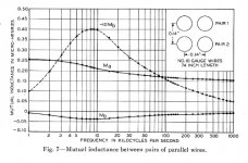
Can this, or part of this, be explained by the asymmetric distribution of current, making the mutual inductance complex in nature (M=Ma+jMb). Supra 2.0 probably have severe proximity issues in the audiorange beeing zip and with the conductors quite closely spaced.
Both Ma and Mb vary with frequency in no easy way changing phase and magnitude with frequency.
I am linking this old article on the topic:
http://www3.alcatel-lucent.com/bstj/vol14-1935/articles/bstj14-2-179.pdf
Attached the real and imaginary parts of the mutual inductance in wires in severe proximity - from the linked article. The mutual inductance is no longer in phase quadrature, but up to 10-15 degrees away from it. Could this explain the phase/delay? And must the hearability test of short t-line remove proximity from the equation?
🙂
Attachments
No.jneutron said:Do you have the article?
Perhaps I don't need to read it, if it is so wrong.scott wurcer said:After review Bateman's plots are fatally flawed, he correctly takes the exact expression for Z0 but for some reason takes the magnitude to keep Z0 real and positive, this is just plain wrong. The equation at low frequencies yields a complex impedance and there is no problem with that. Hence his reflextion coefficients are also wrong.
This business of alleged significant/audible delays on audio cables always seems to come around eventually to either misinterpretation of measurements or miscalculation of theory. Bateman may have done both?
In electronics we have a special name for the part of inductance which is not phase quadrature: we call it resistance.Hedde said:The mutual inductance is no longer in phase quadrature, but up to 10-15 degrees away from it.
In electronics we have a special name for the part of inductance which is not phase quadrature: we call it resistance.
It will lead to higher resistance, thats for sure.
Zm=jwM=-wMa+jwMb , Ma and Mb also being funktions of f.
Is 'python' sorta the new 'c ' ..... ?
It's also the language of the "rapture of the nerds" at the singularity. Python is worth it, it's free and has a huge collection of well supported libraries. Google "Hello World in 7 min." They're right. It's become my goto for quick complex calculations with nice plots.
Let me qualify what I said last night. Bateman's results might have very well been fine for his discussion of RF de-stabalization of amps but is no help in separating phase (he throws it away) from real delay. Remember at HF the line has a real positive Z0 and it does not matter. He does not really explore or need to explore the LF implications. I am in the camp that this problem will yield to lumped element analysis, but am willing to do careful experiments to look at the other viewpoint.
Wavelength of 20kHz wave is 15km, and some are trying to argue with delays on 2m of wire .....
It is definitely a question of HF/VHF interference reflections only and their possible influence on amplifier stability. No low frequency 'smear' here.
It is definitely a question of HF/VHF interference reflections only and their possible influence on amplifier stability. No low frequency 'smear' here.
Last edited:
- Status
- Not open for further replies.
- Home
- Member Areas
- The Lounge
- John Curl's Blowtorch preamplifier part II