Hi John, your TP crossover used a second order filter. In practice would the subtraction method work for higher order cossovers as well, from a TP standpoint? I don't see why not but phase has always confused me to some extent.
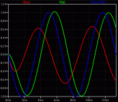
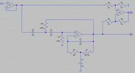
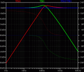
There is no time delay in the subtractive XO circuit you posted. What you have is some group delay (rate of change of phase), meaning that the *envelope* of a wavelet (some sine cycles windowed with a raised cosine, for example) is delayed (the peak of the output envelope appearing later than at the input), but the actual *waveform* isn't. Adding the waveforms yields a new waveform with no group delay, by design (1-x + x = 1).You see, if you look at EITHER output, Hi or Low, they have delay. It can be computed with a computer, or looked up in the tables of a filter book, or whatever. YET, when the two 'delayed' outputs are added back together, the 'delay' DISAPPEARS! Where did the delay go?
Attachments
If a filter introduces an apparent delay which can be removed by an inverse filter then it is not a true delay. True delays can only be removed if you have access to a time machine. Much of the nonsense spoken about 'feedback delays' arises from ignorance of this point.
Well, of course, you guys are right. BUT to me, a crossover had just as much potential delay as a single low pass filter. That is where the surprise came from. I had PRESUMED that a 6dB/octave xover had excess phase shift, because you could measure the 45 degree shift at -3dB rolloff. What was surprising to me was that this phase shift WITH its attendant phase delay, could be easily canceled out. It was even more interesting with the TP filter.
Last edited:
JohnL, YES we often use 3pole filters, even more, BUT the OVERLAP gets even more excessive, AND it is almost impossible to acoustically subtract it out adequately, but IN PRINCIPLE, it is a very elegant approach.
Yes this can be done. JC's circuit is 1st order + 2nd order assymetric slopes.Hi John, your TP crossover used a second order filter. In practice would the subtraction method work for higher order cossovers as well, from a TP standpoint? I don't see why not but phase has always confused me to some extent.
2nd slopes are easy to synthesize this way (see below, different -- non-subtractive -- implementations are possible as well), and I was successful doing 3rd order HP and 2nd order LP (or vice versa). BUT, it doesn't work well in reality, phase difference in the XO region is 120deg or more, killing most of the individual driver signals in the sum, except for distortion compoments. Ranges have high overlap, lobing is horrible. Much better, in my book, is to design for zero phase difference but allowing the overrall allpass which can be easily corrected by inverse filtering the source signal (convolution with the time-inverted impulse of the allpass), that was my point in post 44444.
Hawksford has a XO paper where he presented some higher order XO which have an allpass function of lower order than it would normally have, using the same ideas and having the same drawbacks.
Attachments
If a filter introduces an apparent delay which can be removed by an inverse filter then it is not a true delay. True delays can only be removed if you have access to a time machine. Much of the nonsense spoken about 'feedback delays' arises from ignorance of this point.
You can build up a lumped approximation that within limits approaches what looks like a pure delay. I think some early Apogee filters had a strong sin(x)/x like component in their impulse response with the peak well after the input.
I'm not following you. 45 deg at -3dB is not excess, it is exactly what is expected for a first order filter. No delay, just phase shift. Have I misunderstood you?john curl said:Well, of course, you guys are right. BUT to me, a crossover had just as much potential delay as a single low pass filter. That is where the surprise came from. I had PRESUMED that a 6dB/octave xover had excess phase shift, because you could measure the 45 degree shift at -3dB rolloff. What was surprising to me was that this phase shift WITH its attendant phase delay, could be easily canceled out. It was even more interesting with the TP filter.
Yes, but that is in essence a lumped approximation to a transmission line so it provides an approximation to a true delay. I suppose it could be argued that the true delay occurs when you have an infinite number of infinitesimally small filter sections.scott wurcer said:You can build up a lumped approximation that within limits approaches what looks like a pure delay.
A chap not too far away has those NHTs, with Krell integrated amp and Meridian CD player. Had a listen one evening, system had the usual "hifi" sound, but I very much liked the concept of the speakers - relatively easy to make very physically stable, plenty of room for tweaking ...I now have a pair NHT's just like SY's awaiting the reclaimation of my listening space (still suffering from woofer interuptus). I'll be back in February
I'll find it tomorrow and post a reference.
Well, I was close, but no cigar. G. R. Koonce's article was in _Speaker Builder_ 2/95. His state-variable implemented crossover gives the same results as Erik Baekgaard's filler driver: all pass and constant voltage and second order high pass. It's a superior "transient perfect" tunable crossover. (I mis-remembered in the earlier post: the Baekgaard crossover is B2 rather than LR2).
All good fortune,
Chris
I seem to recall in my sims that the state variable sums flat response with
positive output but you will see a smooth 180 deg shift from low to high
frequency extremes.
😎
correction. I looked it up and it was 360 deg for the summed output.
positive output but you will see a smooth 180 deg shift from low to high
frequency extremes.
😎
correction. I looked it up and it was 360 deg for the summed output.
Last edited:
Now we get back to a point i made almost a year ago when i discovered this Site and decided to put my toe in it (or something)---> The MLSSA "waterfall" plot showing the longer decay at the corner freqs of a LP filter (or HP).
So what happens with this topology cross-over when subjected to same time decay test -- if GD is constant as a non filter - is the time decay also constant at all freqs thru the cross-over ?
Thx-RNMarsh
So what happens with this topology cross-over when subjected to same time decay test -- if GD is constant as a non filter - is the time decay also constant at all freqs thru the cross-over ?
Thx-RNMarsh
Last edited:
Well, the summed response with perfect (or corrected to perfect) drivers can reproduce a square wave. But I'm not smart enough to say that that means it will also meet your criteria. Would be very interested to know, myownself.
Thanks very much,
Chris
Thanks very much,
Chris
Of course real world crossovers are made imperfect by non-coincident drivers, and real drivers' fundamental resonances, keeping geometric solutions like D'Appolito's and driver fundamental resonance shifting (nowdays called a Linkwitz Transform) still in play.
The cool thing to me about Koonce's paper is the idea to sum LP and bandpass, and make the LP driver do both. It's well worth digging out if y'all can. The original Baekgaard is in AES Loudspeakers Anthology (I think).
All good fortune,
Chris
Edit: John Curl is reading my mind! I knew it!
The cool thing to me about Koonce's paper is the idea to sum LP and bandpass, and make the LP driver do both. It's well worth digging out if y'all can. The original Baekgaard is in AES Loudspeakers Anthology (I think).
All good fortune,
Chris
Edit: John Curl is reading my mind! I knew it!
Well, the summed response with perfect (or corrected to perfect) drivers can reproduce a square wave. But I'm not smart enough to say that that means it will also meet your criteria. Would be very interested to know, myownself.
Thanks very much,
Chris
Just to state what I think that means: It means that all of the Fourier components (i.e. at all of the odd harmonic frequencies) still had the correct amplitudes and relative (to each other) phase angles. So the phase angles either had not changed, or, they all had changed by the same constant. So the phase angle change did not vary with frequency. Does that seem correct?
- Status
- Not open for further replies.
- Home
- Member Areas
- The Lounge
- John Curl's Blowtorch preamplifier part II


