John, please don't jump to the conclusion that they are automatically using filters to get that response. The whole point of Terry's post was to point out that it does not have to 'usually' rise. My (limited) experience suggests that designs with a flat THD / f response can perform remarkably well compared to those with THD that rises with frequency.
I understand that Lamm makes this flat response a design goal in their line stages.
Terry, which amps were they?
Ayre MXR, Dartzeel NHB 108
Please, Pavel, sooner or later, non-linear capacitance will add its distortion. Perhaps not ALWAYS at 10KHz, but sooner or later. This is the engineering point that I am trying to convey.
It is not impossible to achieve this goal. One needs to fulfill:
1) very good inherent linearity in all stages
2) high speed
3) high OLG -3dB corner
Is this a power amp into 8ohms or preamp into high impedance
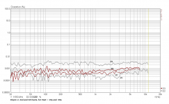
Here is a 250W power amp with a flat response vs frequency. This was plotted at 1W and 10W and the curve is quite well behaved. However, I think if this was done at say 100W or 200W, it would take on a different shape, and distortion would rise at higher frequencies (here I mean at a few KHz for example). This is a 'moderate' feedback design - about 18dB at 20KHz you can see here: http://www.diyaudio.com/forums/solid-state/89380-ovation-amp.html. Note the response drops off at HZ because of the AP's filtering.
(Note: This test was done on 100VAC rails, and the transformer is wound for 120VAC)
(Note: This test was done on 100VAC rails, and the transformer is wound for 120VAC)
Attachments

Even if the signal passed through many opamps during recording process, the sonic result would be affected by specific stages, like CDP output stage, preamplifier, and power amplifier input stage. This is very interesting, and it indicates that neither PIM, nor high order harmonics are the answer.
Or, perhaps this shows something about what the recording process is able to actually "record" and what it fails to record??
_-_-bear
Otala's original PIM analysis kept DC loop gain constant and changed the corner frequency - ie changed the GBW product - little wonder that "high bandwidth" (== high GWB, more gain at higher frequencies) appeared to be "the solution"
but we're usually faced with a fixed GBW due to limited output device speed - so the only way to "increase corner frequency" is to lower DC gain (assuming fixed GBW frequency 1st order compensation)
when the choice is to lower DC open loop gain or allow the the 1st order dominant pole slope to continue, giving more loop gain at lower frequencies (and resulting in the dreaded "lower bandwidth" of the discussions framework) it is clear from theory and measurement presented in peer reviewed journal articles that "lower bandwidth", higher low frequency loop gain gives lower distortions - and doesn't increase PIM vs the same GBW "high bandwidth", low DC open loop gain - I have repeatedly shown this in easily accessable simulations here
those claiming superior listening results from "high bandwidth" circuits need to look elsewhere than the original Oltala "PIM" feedback loop phase shift argument- it is a NON-controversy by every measure except for their clinging to it as an explaination of their perceptions
and yes John, this includes Glibert's Tanh distortion analysis in his "Are OP Amps Really Linear" article as I've addressed in past discussion on the subject here - the engineering conclusion from the analysis Do Not support your case for "high open loop bandwidth" in the fixed GBW, single pole compensation case
This doesn't adress the validity of your and other low/nfb advocates listening tests - but it should close out this thoughly examined theory of the cause
Last edited:
I am concerned with overreaction to various attempts to clarify audio design. EVERYTHING is important, at least to me. EVERY area of audio design could well be improved, from microphone, to speaker. However, applying the SAME test standards to each and every audio device, leaves us in a dilemma, in that a great more loudspeaker distortion is easily tolerated, both in harmonic distortion and frequency response, than with many other links in the chain of audio reproduction, such as amplifiers and preamps.
It may well be that we are measuring the wrong thing, that our ears are NOT most sensitive to.
This can be shown with the Hirata test, that is virtually transparent to loudspeakers and microphones, YET easily separates many amps from each other. Furthermore, the 'good' amps seem to also measure well with the Hirata test. 'Bad' amps, as noted by subjective listeners, measure much worse.
I was certainly surprised when my fairly elegant (in my opinion) AC distortion balance control that I had designed in a line preamp, showed worse performance with the Hirata test, even though the 2'nd harmonic and correspondingly, total harmonic DROPPED with the use of the AC distortion balance control inserted. How many of these HIDDEN problems get around our conventional measurements? What could we be missing, when it comes to the human ear?
as long as these "differences" are only reported by individuals who admit to having no use for ABX or blinding protocols it is likely to be tough going
a honest question - can you still hear these differences when say recording the amplifier output V with a high quality 24/96 or 192 ADC and playing them back over high end headphones with low distortion such as HD600? – after all you do claim they “come through” despite studio signal chains and loudspeaker imperfections adding their own distortions
if so you and others could put together an "instructional" DVD-A of these subtleties for the rest of us to access
Turning in circles, again.
BTW, any additional even 24/192 ADC will put further sound variable into the chain.
BTW, any additional even 24/192 ADC will put further sound variable into the chain.
I realize that PMA, but some might learn a thing or two. Ignoring these problems will not improve anything. I can see from your work, and your schematics that you are very successful in audio design, more than most, that's for sure, but I still like to plug at teaching others, if I can. In return, I often learn something from a 'link' or even a challenge made to me.
Turning in circles, again.
BTW, any additional even 24/192 ADC will put further sound variable into the chain.
so we are here?
The Dragon In My Garage
First of all, JCX, I don't usually use digital for serious evaluation of audio. Only analog master tapes or extra quality vinyl records are my choice. I see great promise for high resolution digital, but even working with some of the most exotic servers, has left me unimpressed and even bored. Why, I cannot say.
What I use is a STAX Lambda headphone system, bypassing the Alps volume control (I can hear it) where the headphones are direct driven by vacuum tubes and the tubes driven by Toshiba j-fets. This is my reference, and it works for me. I seldom use it, because the headphones are relatively uncomfortable, especially lying down, and the overall response is VERY analytical and not very forgiving.
What I use is a STAX Lambda headphone system, bypassing the Alps volume control (I can hear it) where the headphones are direct driven by vacuum tubes and the tubes driven by Toshiba j-fets. This is my reference, and it works for me. I seldom use it, because the headphones are relatively uncomfortable, especially lying down, and the overall response is VERY analytical and not very forgiving.
Loudspeakers, at least the dynamic variety, has distortion that goes down with falling level and rising frequency so they could qualify as "good sounding". On the other hand a lot of progress has been made the last years in terms of distortion and linearity mostly due to the availlabilty of the Klippel Laser Distortion Analyser. I can now routinely design
passive loudspeakers with + - 1 dB frequency response from 200Hz to 20kHz ignoring some diffraction artifacts in the treble. Such a loudspeaker can have distortion as low as
0.1% second harmonic, 0.05% third, 0.03% fifth from 200Hz on at 90dB in 1m and falling with level and frequency, so they aproach the quality of a good tube amp. Distortion from mechanical devices have a different character then electronic devices so the good examples may be at least over a certain dynamic range and bandwidth transparent to flaws in the amplification chain.
Good for you, Joachim. This looks like progress. 90dB is an excellent place to listen. It is LOUD in my listening space.
A pair does 93dB plus difuse field when one speaker has 90dB sensitivity. That´s loud. When i listen VERY LOUD i measure peaks
slightly higher than 100dB but up there the ear starts to compress. I also sit quite close to the speakers, that helps too to reduce power hunger. My right ear starts to distort when i measure more then 7V RMS on one speaker but my MPL is very efficient. I measure 110dB peak from a pair then.
slightly higher than 100dB but up there the ear starts to compress. I also sit quite close to the speakers, that helps too to reduce power hunger. My right ear starts to distort when i measure more then 7V RMS on one speaker but my MPL is very efficient. I measure 110dB peak from a pair then.
Ayre MXR, Dartzeel NHB 108
Thanks Terry (I'll scoot off and see what I can learn about them).
For the record, I just previewed one of Matti Otala's mathematical derivations of phase distortion or PIM in an IEEE paper from 1980. I see nothing wrong with his math or his predictions in this paper. If I understand it right, you have to have a low open loop bandwidth in order to generate PIM. I don't think that a high open loop bandwidth will generate it. Gain bandwidth has little or nothing to do with it.
Otala's original PIM analysis kept DC loop gain constant and changed the corner frequency - ie changed the GBW product - little wonder that "high bandwidth" (== high GWB, more gain at higher frequencies) appeared to be "the solution"
but we're usually faced with a fixed GBW due to limited output device speed - so the only way to "increase corner frequency" is to lower DC gain (assuming fixed GBW frequency 1st order compensation)
when the choice is to lower DC open loop gain or allow the the 1st order dominant pole slope to continue, giving more loop gain at lower frequencies (and resulting in the dreaded "lower bandwidth" of the discussions framework) it is clear from theory and measurement presented in peer reviewed journal articles that "lower bandwidth", higher low frequency loop gain gives lower distortions - and doesn't increase PIM vs the same GBW "high bandwidth", low DC open loop gain - I have repeatedly shown this in easily accessable simulations here
those claiming superior listening results from "high bandwidth" circuits need to look elsewhere than the original Oltala "PIM" feedback loop phase shift argument- it is a NON-controversy by every measure except for their clinging to it as an explaination of their perceptions
and yes John, this includes Glibert's Tanh distortion analysis in his "Are OP Amps Really Linear" article as I've addressed in past discussion on the subject here - the engineering conclusion from the analysis Do Not support your case for "high open loop bandwidth" in the fixed GBW, single pole compensation case
This doesn't adress the validity of your and other low/nfb advocates listening tests - but it should close out this thoughly examined theory of the cause
Hi JCX,
You are EXACTLY right. Completely in accordance with the theory and findings in my PIM paper available at Cordell Audio: Home Page. Your use of the word "clinging" is an accurate description of what is happening when this topic gets brought up over and over again at regular intervals by those who believe that low open loop bandwidth and high NFB at low frequencies exacerbates PIM. Those who make these assertions should also stop citing Barrie Gilbert for support, as his analysis DID NOT support this assertion.
Cheers,
Bob
For the record, I just previewed one of Matti Otala's mathematical derivations of phase distortion or PIM in an IEEE paper from 1980. I see nothing wrong with his math or his predictions in this paper. If I understand it right, you have to have a low open loop bandwidth in order to generate PIM. I don't think that a high open loop bandwidth will generate it. Gain bandwidth has little or nothing to do with it.
Hi John,
You do not have to have low open loop bandwidth to generate PIM. Otala in fact failed to address the case of high open loop bandwidth when the gain crossover frequency was kept the same. Had he adrressed that condition in a proper context, he would have found that the generation of PIM is the same. It is the movement of the closed loop pole, not the open-loop pole, that generates PIM.
Cheers,
Bob
- Status
- Not open for further replies.
- Home
- Member Areas
- The Lounge
- John Curl's Blowtorch preamplifier part II