Yes, I'm in general agreement with VladimirK, the key is that no signals except those are supposed to be there are to be found within the circuitry.
I've done simulations of what really happens in power amps when the full chain from the mains supply through to the voltage rails is reasonably well modelled, with a somewhat complex signal driving it at high level, into just an ideal load - and it's a very nasty mess indeed ...
I've done simulations of what really happens in power amps when the full chain from the mains supply through to the voltage rails is reasonably well modelled, with a somewhat complex signal driving it at high level, into just an ideal load - and it's a very nasty mess indeed ...
Yes, I'm in general agreement with VladimirK, the key is that no signals except those are supposed to be there are to be found within the circuitry.
I've done simulations of what really happens in power amps when the full chain from the mains supply through to the voltage rails is reasonably well modelled, with a somewhat complex signal driving it at high level, into just an ideal load - and it's a very nasty mess indeed ...
I guess, that your simulations were based on a standard software, and probably your results did not include EMF interference effects, i.e. they are not a complete story. I imagine how difficult is to simulated complete 3D amp structure, including EMF (I mean mutual "inductances" and "capacitances" between various parts of amp). However, designers of classD modules are forced to do such a complex simulations.
Last edited:
Thanks Vlad for your input. Of course, you and fas42 are on the right track. (in my opinion)
I design audio equipment that sometimes has to work WELL at extremely low levels of both voltage and current. What happens at those really low levels and whether is it as linear as commonly assumed, is my real pursuit. Do all wires and connections act 'perfectly' without adding distortion OR losing information at all levels and at all times? I started out on this pursuit about 20 years ago, and I am still interested in any input that gives me more insight.
I design audio equipment that sometimes has to work WELL at extremely low levels of both voltage and current. What happens at those really low levels and whether is it as linear as commonly assumed, is my real pursuit. Do all wires and connections act 'perfectly' without adding distortion OR losing information at all levels and at all times? I started out on this pursuit about 20 years ago, and I am still interested in any input that gives me more insight.
Using LTspice, and I didn't include externally generated EMF ... I used a far more realistic AC mains waveform, none of this 0% distortion, pure sine wave, nonsense normally applied - so, somewhat flat-topped; then the combination of reasonable transformer parameters, rectifier and smoothing caps guaranteed great swathes of HF noise running around - plenty of interference nicely generated within the schematic itself ...
So, yes, I could have made it much worse ...
An exercise I did some time ago was to take one of the latest Bob Cordell models and look at what was going on: at high power levels some very nasty current waveforms could be found in parts of the circuit - so, just introduce a little bit of stray inductance, or capacitance, there, and guess what happens ...
I also wondering, what the sence to simulate, by putting some ideal voltage sources at the rails, since everybody knows that kinds of caps used at rails affect sound, not speaking about other things.
Thoughts that pop into my mind when I come here -->
I'd explain it to you, but I'm out of puppets and CRAYONS
Welcome to AWESOMEVILLE.
Population: ME
I'd give up drinking, but I'm not a quitter.
<3
-RNM
I'd explain it to you, but I'm out of puppets and CRAYONS
Welcome to AWESOMEVILLE.
Population: ME
I'd give up drinking, but I'm not a quitter.
<3
-RNM
Now a better way to test if CD's can be annealed and improve the sound would be a microwave oven
or even more practical a dip in hot water. If the gizmo produced heat you gotta think someone would have noticed!
So if anyone wants to test the theory all you need is two identical CD's, listen to them both to see if you can hear a difference and then dunk one in cold water and the other hot. A lot easier and less expensive than waving a magnet.
ES
Simon
Microwave oven heating is rumored to shatter a CD due to wave reflection from the aluminum, causing standing waves in the cavity. [Possible danger]
or even more practical a dip in hot water. If the gizmo produced heat you gotta think someone would have noticed!
Annealing alum at temperatures that will not damage the plastic, will give you at very best 1% tensile strength reduction.
Recrystallization is also out of question.
As for the disk edge treatments, if one read only on optical design, he will realise that such treatments have no hope of affecting data readout.
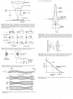
(Attachment is from John Watkinson’s very telling book “The Art of Sound Reproduction”
Years ago I had hand bevelled and painted black the edges of very many CDs.
George
Attachments
Last edited:
Have a look around Dr Howard Johnsons site, also look up high speed digital and signal integrity. Do a DDR interface and you have to simulate it using quite complex software (3d field solvers etc).
Signal Consulting, Inc. - Dr. Howard Johnson
And a very basic but illustrative PDF on current flow...
http://www.x2y.com/filters/TechDay0...log_Designs_Demand_GoodPCBLayouts _JohnWu.pdf
We deal with very high frequency digital design every day in the real world, where parasitics are a killer, how relevant to audio frequencies it is (apart from controlling EMC issues) I don't know, but we deal with wave propagation every day. There was a good thread covering a lot to do with signal propagation at audio frequencies, and the current Cable thread has some good information in the last few days from JN and others, worth a read if you want info on current flow.
http://www.diyaudio.com/forums/everything-else/193100-speaker-cable-myths-facts.html
I plead guilty everyday.
(There’s no hope for me. I’ll come back on earth -at best- as a cockroach)
George
Annealing alum at temperatures that will not damage the plastic, will give you at very best 1% tensile strength reduction.
It's vapor deposited, so annealing and tensile strength aren't factors.
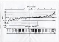
A piano for example is tuned to an equal tempered scale, perfect octaves but the top octaves are "stretched" and sharpened a few cents (because that sounds better to the ear) and the lower bass octaves are flattened for the same reason.
Mooly,
This is a peculiar take on what constitutes an equal tempered scale. Are you saying that tunings exist in which each subsequent octave is not an exact doubling in frequency of the preceeding scale?
Surely, the exact intervals within an octave have to be 'stretched' in order to align with the other mathematical universe of logarithms, but this takes place within an octave, not between octaves.
Why are the inactive ingredients "inactive" in the case of burns. That list does not
In herbs there have been found some inactive ingredients that act as prodrugs, turning active through metabolic processes of the body.
The degree of this conversion and the effects of the resulting activity (Pharmacokinetics), depends greatly on each individual biological details.
George
It's vapor deposited, so annealing and tensile strength aren't factors.
Thanks for confirming.
SY, what is the thickness of alum deposition?
I am wondering what is the +/- of it’s thickness. The pits are 150nm deep
George
Mooly,
This is a peculiar take on what constitutes an equal tempered scale. Are you saying that tunings exist in which each subsequent octave is not an exact doubling in frequency of the preceeding scale?
Surely, the exact intervals within an octave have to be 'stretched' in order to align with the other mathematical universe of logarithms, but this takes place within an octave, not between octaves.
This shows how an experienced tuner might tune a particular instrument. Its always a matter of compromise and what "sounds right" for a particular instrument.
Also,
Piano tuning - Wikipedia, the free encyclopedia
Hmmm, one learns something new every day: Inharmonicity - Wikipedia, the free encyclopedia ...
All part of the problem.
Attachments
SY, what is the thickness of alum deposition?
Nominally, about 50nm.
Anticipating Ed's reply, that layer's thickness can vary with altitude as the gravitational field changes. Likewise, if the CD is played vertically, the thickness changes, though small, are real and will follow the rotation. You just have to have sensitive enough measurements to detect this, and be willing to eschew the use of error bars. The changes in disc eccentricity and diameter could be the "X-factors" in better CD playback- I may have to start marketing a gadget to fix this hitherto-ignored problem.
SY
You and George have almost anticipated and ruined the rest of this.
For example I have found a few minutes in a microwave really does improve many of the heavy metal CDs.
As to the warm water dunk, I strongly suspect it will improve older CDs. But the mechanism will not be from any metallurgical change. In case you never noticed CDs even in storage get a thin film on the surface. Same sort as on the inside of a car's windshield.
I repeat the conclusion. Waving a magnet or any other treatment will not alter the file size of a CD.
Now you have raised an actual issue. That is the repeatability of a CD to have the exact same rotational axis when you remove and reinsert it. The obvious issue is that the total error should be less than 1/2 of a track width. As the spindle is molded plastic and nothing is really round including the CD mounting hole a small rotation in the alignment between the two will change the axis of rotation.
That movement does change tracking demands and both the power supply variations and the noise from the tracking system. So even with error correction there can be differences before and after "treatment". Even if the treatment is the classic put in in a brown paper bag and swing it over your head!
Now for some serious stuff. Let us talk about modulation transfer function as used in optics and diffusion in a noinear medium.
ES
Last edited:
That movement does change tracking demands and both the power supply variations and the noise from the tracking system. So even with error correction there can be differences before and after "treatment".
And yet, one doesn't see problems in the analog output (the only part that counts). Why do you think that is?
- Status
- Not open for further replies.
- Home
- Member Areas
- The Lounge
- John Curl's Blowtorch preamplifier part II