Well, I will summarize about servos, rather go into extended length with them. Two examples have been shown already, and they, or variations of them are what I use almost exclusively. You can also create a servo that controls offset by using the current passing through its V+ and V- power terminals, but I won't discuss it here.
The most serious problem with servos seems to come from the effective bandwidth of the servo, usually being too high, so that the servo sometimes dances along with the music, OR it tries to make symmetric a non-symmetric low frequency waveform as far as its short term DC offset is concerned. Therefore, my advice is to keep your servos very sluggish, even to the point where first turn on takes an observable time to settle.
The next strong suggestion is to not tightly couple the IC op amp very tight to the input of the main amp or preamp. This will mean a build out resistor of some magnitude from the output of the servo to the main amp to make an attenuator. Make the servo work for fixing the offset, for example 3V offset on the servo amp, might be 30mV at the input of the main amp. This way the servo IC, which always has some defects, is buffered from the main amp stage. This also says that even if you could easily servo out an almost completely unmatched assemblage of input parts, if you connected the servo directly to the input, you would do better with a limited effective servo range, and better matched parts at the input, since then you can have more buffering between the servo, which should only be used to maintain a 0 DC output, and nothing else.
Last edited:
Thank you, John.
The question I asked was:
If I remember correctly, the servos designs by you which were copied, or emulated here, do 2 different things. 1 is to compare the outputs DC levels to the ground level and keep the outputs DC at ground level. The second is to compare end equalize the DC level between the 2 outputs.
Now, once both outputs DC level is kept at the ground DC level, why is it necessary to compare and equalize the DC level between the 2 outputs?
The servos are kind of stupid. One can match the outputs to each other. The other can find ground. You have to work with them both to see what happens.
If you guys truly wanted to test my opinion then you would give me a system to beat. I can't beat a system at the fraction of the cost if I don't have something to work from.
I can't resist this challenge.
Let's start with one single component, before we get to a system approach (which is far more complex). Ok? Can you do that?
Ummm... let's think really hard about it and come up with some single component to "beat".
Ah ha! By jove, I've got a capital idea!
How about a preamp??
Yeah, a preamp. Now which one?? Ummm... ok, how about a BLOWTORCH?
Beat a BLOWTORCH, Key.
Your turn. Show us what you've got.
_-_-bear
The servos are kind of stupid. One can match the outputs to each other. The other can find ground. You have to work with them both to see what happens.
So would that mean that if one was not at absoloute ground then it would lift the other off absolute ground... perhaps pull it down - who is the master and who is the slave? ...or are you suggesting that ground is not where it seems to be WRT an output stage - some sort of Vdrop issue??
The servos are kind of stupid. One can match the outputs to each other. The other can find ground. You have to work with them both to see what happens.
I don't get. Once one servo keeps both outputs DC at ground level, why should we bother compare them?

Wouldn't it be nice to bring anything constructive here??
My suggestion - let's discuss idle current of the input JFEts.
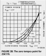
Zero tempco point or as close to as possible.
Zero tempco Vgs = Vp+0.63V where Vp is the "pinch off" voltage (g-s)
For the Toshiba high gm types it is very close to Idss.
Attachments
I don't get. Once one servo keeps both outputs DC at ground level, why should we bother compare them?
Half the potential offset. Of course, if the opamps are decent (and they don't have to be fast, just low offset), that's probably not important.
Half the potential offset. Of course, if the opamps are decent (and they don't have to be fast, just low offset), that's probably not important.
Sorry, I don't get what you mean by half potential offset.
Zero tempco point or as close to as possible.
Zero tempco Vgs = Vp+0.63V where Vp is the "pinch off" voltage (g-s)
For the Toshiba high gm types it is very close to Idss.
There is another zero TC point which is useful. Where any Idss FET from the distribution will have "zero" TC of drain current when used as a current source via a source resistor. This is typically at a low current (below the Idss for any of the FET's).
Sorry, I don't get what you mean by half potential offset.
Let's assume that an opamp has a max offset of +/-x. That means that if you have opamps controlling each side of the preamp output, the max offset will be 2x, if each is at the opposite end of the spec. Now, if you have one opamp controlling one side of the preamp output and the other controlling the differential voltage, the other opamp will bring the other side to within x, i.e., half the worst-case offset of the other configuration.
In the real world, that's only something like a millivolt versus half a millivolt, so it's not like this is a Big Advantage.
It is important to use two servos with a differential out line stage. This is because you can have a deviation from ground, and separately a deviation between each separate output. When you are differentially comparing the two outputs, you lose track of ground. When you are comparing the two outputs to ground, you lose the difference between the two outputs. Of course, the LF411-2 in the old schematic can be replaced with the OPA134 and OPA2134. That is what I use, these days. Better accuracy and lower noise.
For the Toshiba high gm types it is very close to Idss.
Yes. And you work in a most linear portion of the transfer characteristics and get lowest noise as well. Interestingly enough, most even well known designers run the JFETs at low idle in audio preamps. Like 2mA for a 10mA Idss device. Any good reason to make it so? I can guess the only one - part selection not needed then.
I'm rather the one , who want to lern a lot from this tread 😉, but mayby this is the explanation
citing Mr Borbely
"..............
I have measured the input capacitance
for the amplifier in Fig. 7, both
with and without RS. Without RS, the capacitance
was over 600pF! With RS =
100Ω, the input capacitance dropped to
127pF, because of the local feedback
through RS...."
"......
The input capacitance of the
circuit in Fig. 9A is approximately
160pF, so the cascoding indeed
reduces the input capacitance.
Further reduction is
achieved by adding local feedback
with RS (Fig. 9B). The
input capacitance is now reduced
to 50pF. With such low input
capacitance there is no longer any
danger of creating a low-pass filter
with the volume control..........."
It is important to use two servos with a differential out line stage. This is because you can have a deviation from ground, and separately a deviation between each separate output. When you are differentially comparing the two outputs, you lose track of ground. When you are comparing the two outputs to ground, you lose the difference between the two outputs. [snip].
But then, if you control both outputs separately to gnd, they are automagically controlled as to the differential offset, isn't it? Two outputs close to gnd are also close to each other.
jd
Yes, that is another way to do it, but you would still need two servos - one each for the outputs.... if you control both outputs separately to gnd, ...
With JC's approach, one servo compares the average of the two outputs with ground and applies a common-mode adjustment while the second servo compares the two outputs with each other and applies a differential-mode adjustment.
- Status
- Not open for further replies.
- Home
- Member Areas
- The Lounge
- John Curl's Blowtorch preamplifier part II