This is good for you Scott. Ed’s invitation calls for liver troubles.
But if you have the chance, try smoked (fume) Grappa from Italy.
Behind the slider, with older console modules, attenuators were not simple potentiometers.
George
George,
Sip a small glass, it is not water!
A slider with carbon composition resistors! The first Yamaha mixers (PM1000) used a rotary pot with a mechanical slip roll to make it into a slider!
In one of my test setups the Lorlin silver plated rotary switch produce enough distortion you could reliably tell one of the positions!
ES
forget the sqrt(R) dependency?
most like to use the 4.something nV/sqrt(Hz) for 1 kOhm room or calc for operating T
Johnson?Nyquist noise - Wikipedia, the free encyclopedia
while popular with datasheet writers the "distortion magnification" completely misses input impedance nonlinearity - which often dominates today with fet input and > kOhm source
Last edited:
Ed this is bad setup, because the capacitance between input wire and the output node is varied between setups and uncontrolled
Ed this is bad setup, because the capacitance between input wire and the output node is varied between setups and uncontrolled
Can you suggest a better method? I suspect their should be some difference between C coupling and what we are looking for. (The second setup may show this.)
forget the sqrt(R) dependency?
most like to use the 4.something nV/sqrt(Hz) for 1k room or calc for operating T
Johnson?Nyquist noise - Wikipedia, the free encyclopedia
Typo 1 Pa across 1K, but it won't affect much!
Ed this is bad setup, because the capacitance between input wire and the output node is varied between setups and uncontrolled
wire both paths with something rigid, switch source far from bridge to one or the other path - then the potential is same on all the wiring (less wire Z effects) and just the current path changes ?
another verification/calibration/control would be to replace bridge with "star bridge" 4 equal arm cross to see any coupling/phase shift effects in just the wiring, sw, setup while keeping the load conditions very similar
my guess is that you'd be looking for uV/V from mutual inductance/proximity effect at even 10 kHz - do you have the AP with the 1 MHz ADC?
Last edited:
JN
I just picked 4 10.000K Dale CMF resistors. To my surprise I only had to go through the first 60 to get a match! Tolerances are quite tight. Worst I saw was 10.032K
I just picked 4 10.000K Dale CMF resistors. To my surprise I only had to go through the first 60 to get a match! Tolerances are quite tight. Worst I saw was 10.032K
That should be no surprise - especially if they are bandolered as they would only be mS apart in manufacture time.
A process with enough slop in it to produce big variations from one device to the next would be very cheap and nasty, and, more to the point, difficult to keep tuned.
A process with enough slop in it to produce big variations from one device to the next would be very cheap and nasty, and, more to the point, difficult to keep tuned.
Are they Laser trimmed by production process ?I only had to go through the first 60 to get a match! Tolerances are quite tight.
JN
Scott,
Don't pull the rope! It is not a snake or a tree or even a wall. Don't pull the rope
Pull that rope Scott instead

Colosseum "Rope Ladder To The Moon" - YouTube
George,
Also note almost no one else even understands what we have been discussing!
Ed, you are wrong on this.
Definitely, there are many people here that understand the talk, alas I am not among them!
(where is the description of your 10 resistor method?)
When they first did their setup they used higher value resistors. (So please don't give me they know what they are doing line... everyone makes missteaks.) I did tease BP about it and never got a reply, but the next time I looked they were using much lower value resistors.
ES
Is it this Ed?
http://www.eettaiwan.com/STATIC/PDF/200811/20081105_NS_AN03.pdf?SOURCES=DOWNLOAD
some further links for you out there 😀
this one with some details on noise
http://www.angelfire.com/ab3/mjramp/distortiontest.pdf
a more complicated method for very low distortion measurement
http://www.analogzone.com/tmt_1002.pdf
George
How do you define "signature" ?Fixed resistors are easier to find that are pretty good and reasonably low priced, but they also suffer from distortion and 'signature'....
...Audiophile for the sound, engineer for the measured distortion...IF you want the best fidelity possible.
Response curve ? Noise ? distortion ? Mechanical effects ?
Who defines what is "audiophile ? And on witch criteria ?
Very nice, but I prefer the original Jack Bruce version...😀
You hardcore guy.🙂Very nice, but I prefer the original Jack Bruce version...😀
I should have linked to the “Lost Angeles” but it wouldn't have matched the subject.
George
George,
A slider with carbon composition resistors
ES
1960 era. Full class A circuitry (2n1711 heatsinked all-over, 6-7 expensive large precision resistors, shielded and internally screened input-output transformers, on board heavy LC for the 24V already stabilized DC, ect.
Sip a small glass, it is not water!
Men’s talk.
My liver medical exams were long (14 years) red after my beatnik years. My second wife was the benign bitch to save me by a hair width.
Colosseum - Those About to Die (1969) - YouTube
Now I am a good boy. The usual suspects are still my friends but only occasionally.
With such talk, you made me spin records from that time and it’s only 22:00 Friday night. 😀 What a mesh!
George
Ed, you are wrong on this.
Definitely, there are many people here that understand the talk, alas I am not among them!
(where is the description of your 10 resistor method?)
Is it this Ed?
http://www.eettaiwan.com/STATIC/PDF/200811/20081105_NS_AN03.pdf?SOURCES=DOWNLOAD
some further links for you out there 😀
this one with some details on noise
http://www.angelfire.com/ab3/mjramp/distortiontest.pdf
a more complicated method for very low distortion measurement
http://www.analogzone.com/tmt_1002.pdf
George
George,
The links are nice, but I believe the NS/TI note was revised when it was realized that the original setup had too much resistor noise. Note the use of the 10 ohm load and 10 ohm source resistor in the National TI ap note. The AP system 2 has as the minimum value 20 ohms, although on the BNC output you can set it to 50 and 600 for the XLRs.
They do mention that they were measuring .2 ppm and the technique is limited to .1 ppm, so I think they know they were down in the dirt. Now they were using the AP system 2 and Scott uses a more modern and less limited analyzer!
Now the NS/TI method I think is better than the other ap note using additional buffering. I think that was more useful when analyzers were more limited.
But I think my conclusion that they were understating the performance of their chip is correct.
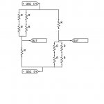
As to the ten resistor method I though you were following when I showed that here. But I've attached it. I did note a small drawing error, but you'll get the idea. If the resistors are perfect there is no output.
BTY I have never done a cancellation type test on active components, so I can't offer any useful insight.
ES
Attachments
Last edited:
George,
As to the ten resistor method I though you were following when I showed that here. But I've attached it. I did note a small drawing error, but you'll get the idea. If the resistors are perfect there is no output.
ES
I have missed that Ed. Thanks. I’ll dig on the description of this bridge tomorrow.
The links are nice, but I believe the NS/TI note was revised when it was realized that the original setup had too much resistor noise.
In the first link, Fig.1 is with the high Rs (1M/1M/1K. Note the Cx). Fig.3 is probably the revised one with 1K/10 Ohm.
As for Fig. 1 set-up, see also the first article (Fig.4, Fig.7) in here
http://www.google.gr/url?q=http://application-notes.digchip.com/006/6-8794.pdf&sa=U&ei=jD3wUOyiDuTY0QX0r4GIBQ&ved=0CBQQFjAA&sig2=nMtI2PTMspvdB27WUuw3uw&usg=AFQjCNHJxTu0zuJk2WiRnaVwztDaBdWFiA
George
I have missed that Ed. Thanks. I’ll dig on the description of this bridge tomorrow.
In the first link, Fig.1 is with the high Rs (1M/1M/1K. Note the Cx). Fig.3 is probably the revised one with 1K/10 Ohm.
As for Fig. 1 set-up, see also the first article (Fig.4, Fig.7) in here
http://www.google.gr/url?q=http://application-notes.digchip.com/006/6-8794.pdf&sa=U&ei=jD3wUOyiDuTY0QX0r4GIBQ&ved=0CBQQFjAA&sig2=nMtI2PTMspvdB27WUuw3uw&usg=AFQjCNHJxTu0zuJk2WiRnaVwztDaBdWFiA
George
I think you found it. They started testing with a 1K resistor which changes the 2.7 nV of input noise to 2.9 nV even before any other noise issues. When they dropped to 10 ohms they went low enough that I think the AP system 2 could not drive the circuit under test beyond 5 volts. So the real question is if the test equipment can only be made out of the parts you are testing....?
So the THD may actually be limited by the passive components. Particularly when you use the wrong parts. However that is not the entire story as shown in that paper. But the LM4562 has another issue. It picks up EMI like crazy. When you provide proper input protection it works better.
The one issue that I think is still open is does the opamp clip internally under any funny conditions. But there is so much heat on that I'll leave those issues and tests for others.
ES
This is good for you Scott. Ed’s invitation calls for liver troubles.
But if you have the chance, try smoked (fume) Grappa from Italy.
George
Today all I wanted was a big serving of avgolemeno, so I made my own. Our local Greek community has seemed to dissapear.🙁
- Status
- Not open for further replies.
- Home
- Member Areas
- The Lounge
- John Curl's Blowtorch preamplifier part II