The ABX box with the mercury relays was the so called Spiegel box. Made by an audio designer who gave up audio design after using his test box.
I did a search on the 5A mercury relays used, and found out all kinds of useful (to me) things.
I did a search on the 5A mercury relays used, and found out all kinds of useful (to me) things.
May i ask the gentle non autistic contributors generous enough to share their experiences to give some details about, in order we, poors heretics, can pick some interesting conclusions from your reports:
If the commutation was on line level or loudspeaker level.
If line level, what was the order of the input impedance.
If loudspeaker signals, what was the average power.
And in both case, if any noticeable decrease of sound quality, to try to describe-it ?
Thank in advance.
If the commutation was on line level or loudspeaker level.
If line level, what was the order of the input impedance.
If loudspeaker signals, what was the average power.
And in both case, if any noticeable decrease of sound quality, to try to describe-it ?
Thank in advance.
Indeed, a very original way to proceed.I'm contemplating the nightmare of an infinite regress of ABX boxes testing ABX boxes.
John,
Thanks for the useful input here is the revised version.
Pavel will find the integrator interesting as it uses a prone to overload chip. The data sheet shows some interesting quirks.
ES
It looks like you are trying to lock a VCO to an external oscillator (it says rubidium). For the input conditioning from the external source there are a number of good solutions, start here: Oscillator Waveform Conversion. The manual for the Lpro here http://www.ko4bb.com/Manuals/05)_GPS_Timing/Datum/LPRO/Datum_LPRO-101.pdf starting at page 16 has specifics on interfacing for lowest phase noise. The Wenzel site has good info on type 2 PLL's for this.
However I would question where getting the frequency of the master clock slightly better will be ever detectable, let alone by ear. I would use a GPSDO as a source instead of a Rubidium, no wear out mechanisms. But a good crystal oscillator would be far more imporatant.
Pavel will find the integrator interesting as it uses a prone to overload chip.
For my customer, high power testing lab, I have built about 10 integrator amplifiers for Rogowski coil sensors. They were designed to operate from 0.01Hz to some 50kHz. The integrator amplifier is a specific task, in case you need to get high output voltage swing at higher frequencies. For the reason of > 1uF FB cap, it was absolutely necessary to use an additional buffer in a FB loop.
Good cap test as well. Polypropylene OK, polyester (mylar) pretty bad.
Cheers,
We're busy staring at the ground and drooling.
For these busy moments 😀 I suggest a site with real “Real input “ my oh my!
SynAudCon Educational Resources Synergetic Audio Concepts
Better search by author.
Dr. Patronis on EM and coaxials is realy educative (if you don’t want to pay a visit to Heaviside writings)
George
It looks like you are trying to lock a VCO to an external oscillator (it says rubidium). For the input conditioning from the external source there are a number of good solutions, start here: Oscillator Waveform Conversion. The manual for the Lpro here http://www.ko4bb.com/Manuals/05)_GPS_Timing/Datum/LPRO/Datum_LPRO-101.pdf starting at page 16 has specifics on interfacing for lowest phase noise. The Wenzel site has good info on type 2 PLL's for this.
However I would question where getting the frequency of the master clock slightly better will be ever detectable, let alone by ear. I would use a GPSDO as a source instead of a Rubidium, no wear out mechanisms. But a good crystal oscillator would be far more imporatant.
OK you've convinced me to add the two bias resistors. However note the actual output is direct coupled and runs at 3.3 volts
The rubidium standard is the Stanford PERF10 Rubidium Frequency Standard - PERF10 which can lock to a GPS source for long term stability. The rated life of the lamp is greater than the design life of the system.
The VCXO details are not given on the schematic. It uses peltier devices to cool it. There are a few tricks in mounting it to reduce vibration transmission. Jitter is in the reasonable picoseconds range.
Using this quality of reference adds 0.12% to the cost of the entire system. The master clock syncs over 200 slaves.
As to the nice references, I can't disagree with the techniques shown, as I am using them to recover the signals from the fiber with them. Jitter is below what my AP can measure.
Schematic attached.
Now the issue is what will it take to measure the jitter?
Attachments
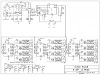
For my customer, high power testing lab, I have built about 10 integrator amplifiers for Rogowski coil sensors. They were designed to operate from 0.01Hz to some 50kHz. The integrator amplifier is a specific task, in case you need to get high output voltage swing at higher frequencies. For the reason of > 1uF FB cap, it was absolutely necessary to use an additional buffer in a FB loop.
Good cap test as well. Polypropylene OK, polyester (mylar) pretty bad.
Cheers,
Nifty! 🙂 Will have to remember and steal the idea as my own. Thanks.
I'm surprised the mercury units did poorly, but your letter to the editor indicates that perhaps the problem was that the overall design of the relays was poor, and the benefit of the wetting was insufficient to counter those deficiencies.Well, I guess I can start.
The worst contacts that I ever came across were sealed mercury relays in an ABX box. The best contacts I have used are Shalco silver rotary switches that we used in the CTC Blowtorch.
So, a very good electromechanical switch which then added mercury wetting to its features could be an excellent unit ... would that be fair comment?
I should also mention that I like silver, in the various contact enhancement forms. Many people seem to have had bad experiences with the stuff, but I suspect sloppiness in using it is the cause of that. Like everything in the audio game, technique is a major part of the battle ...
Frank
Fas42, I appreciate your input. I did define a specific mercury relay as problematic, but I can't be sure of every type of mercury relay. However, think about the materials necessary that will not dissolve in the mercury. A highly marginal lot of material. I would not make a wire from it.
I would also mention, again, that using a subtractive strategy to optimise audio to me is the only way that makes sense, for gaining understanding. Meaning, start with a zero compromise setup, go absolutely silly on everything you can think of that may effect SQ, until that reaches an acceptable level. Then, one by one, back off on each of the OTT techniques to see if that makes an audible difference, until a happy medium is achieved.
This is something like shaving metal somewhere off a high performance vehicle to save weight, until that part breaks; then just add a bit back in again to give an adequate safety margin.
Frank
This is something like shaving metal somewhere off a high performance vehicle to save weight, until that part breaks; then just add a bit back in again to give an adequate safety margin.
Frank
Last edited:
We're busy staring at the ground and drooling.
*scribbling note* Drool cup stocking stuffer for SY...
se
Deep in a swamp in eastern Massachusetts there is a secret labyrinthine man-cave that hosts an annual Christmas party for the local design community. This ritual has gone on for over 30yr. This is where we celebrated SY and jneutron’s birthday (in abstentia) as well as Christmas.
1 – They all work (of course) 2 - spare parts 3 – An appropriate wine
1 – They all work (of course) 2 - spare parts 3 – An appropriate wine
Attachments
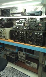
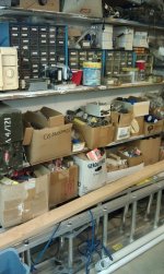
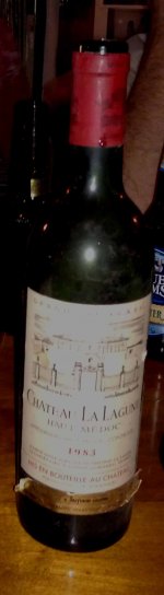
I'm pleased to see examples of aging of cardboard containers, in neat rows, as a way of improving the contents. At least the audio community learnt one thing from the wine industry ... 😉2 - spare parts
Frank
Scott,
Some of that equipment looks like it is vintage my birthday in the 50's. You say it all works... Does that mean that the owner, if not you, needs to turn that equipment on, on a regular basis to keep the electrolytic caps happy? If yes how often would that need to be? Real questions here......
Some of that equipment looks like it is vintage my birthday in the 50's. You say it all works... Does that mean that the owner, if not you, needs to turn that equipment on, on a regular basis to keep the electrolytic caps happy? If yes how often would that need to be? Real questions here......
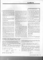
There's loads in that article I'm tempted to pontificate on and in fact have crossed swords with John At in da dim & distant past. eg I worked with Peter Fryer on the stuff in the page 1 footnote.There are a lot of people in the audio game, I was not aware of her before; quite a character it seems! I guess I'm flattered ... and, in looking around for mentions of her found this piece by John Atkinson: Is It Real? Or Is It... | Stereophile.com. Don't agree with everything here, but it has some interesting points ...
But I can pronounce with certainty on one item. His Krell KSA-100 will clip often with KEF R107 when attempting any semblance of accurate piano reproduction in a domestic room. I've tried exactly this combination though I've no idea what is a Klyne SK5. In fact a 1000W/channel amp will also clip but less often. 😱
That's not to say that most people won't consider reproduction of the above system very good.
- Status
- Not open for further replies.
- Home
- Member Areas
- The Lounge
- John Curl's Blowtorch preamplifier part II