Darwin had a better explanation and you don't even need to know it to participate!
Tell that to the handyman who put a whole house plastic body water filter in at the entrance without bypassing it with a safety bond jumper. Then when the dishwasher which was also installed by a handyman...had it's safety bond fail.
Eventually, the dishwasher energized the supply plumbing throughout the house as a result of an internal failure. As a result, the hot and cold feed pipes rose to 120 volts whereas the copper DWV plumbing still went to earth.
The homeowner's wife was taking a shower, the cast iron tub was earthed, the supply runs were at elevated voltage. She was the path of least resistance.
An explanation of "darwin" would probably not be the best thing for her husband to quip...as darwinism would indeed have applied to him immediately after such..😉
j
Interesting commentary KBK, especially when you are careful to keep it 'simple' enough to get where you are coming from, or in other words, understand your point of view.
You seem to have bypassed traditional science/engineering for the search of 'what is really happening'. I applaud you for this, and it is an eye-opener. (when I can understand you)
As I have had phone conversations with you, without any real problem in communication between two people like us, it always surprises me how difficult it normally is to understand what you are trying to convey here most of the time. However your recent input was very clear, and it again reminded me of the quest for 'true' understanding and how difficult it is to get it from traditional engineers and physicists.
By 'true' understanding, I mean how physicists, and even engineers will see the 'world view' of how things work, perhaps 100 years from now.
Your interchange between you and Jneutron, reminds me of the interchange between Lord Kelvin and Oliver Heaviside, perhaps 130 years ago. We all know who won.
You confuse randomly coined buzzwords and reality. The fact that you have no understanding of what was said does not mean it is above your intelligence. Sometimes, a skunk is just....a skunk..You seem to have bypassed traditional science/engineering for the search of 'what is really happening'.
His recent input was a kludged together set of disjoint concepts put together in an attempt to explain what he does not understand.However your recent input was very clear, and it again reminded me of the quest for 'true' understanding and how difficult it is to get it from traditional engineers and physicists.
Sometimes it is better to learn what is going on, or allow those who actually do understand explain it.
Invoking names from the past in an ill-based attempt at trying to raise floobydust to that of understanding is transparently, inaccurate.
Next thing you know, somebody will be trying to explain how the metallic grain structure of an IC causes measureable distortion, when the reality was that the test equipment didn't isolate input ground from output ground in a common chassis..like the 1700 of old...vs the AP.. Remember the ground loop you chased for years John? The first thing I asked you to do was correlate shield resistance, contact resistance and your measurements.. You never did, nor did you baseline your equipment, so eventually, somebody used an AP to repeat your tests...with no data consistent with yours.
Remember you kept seeing tv horizontal scanning in your measurements? That's one of the first things you get when you do not control currents..which is what your STS rig did...failed to control currents.
j.
Last edited:
Milton Ericson used language with undefined semantic in therapeutic sessions. Patients were pleased that such smart fellow talks to them seriously, and they were even getting some wise information from his lectures. But why they worked, he incorporated in his speech sensory - related information that programmed subconscious mind for positive changes.
Jneutron, I liked your input as well, but I wanted to address KBK first, because he is the one usually rebuked here, the most.
Now, attacking someone who does not think like you, is unfortunate. How do you know that you are not losing some important concept, that you might be able to use?
Of course, you are satisfied with what you know, but maybe I might want to hear what KBK has to say?
Now, bringing up my wire test, as an 'attack' on me, is 'over the top'. First, we are NOT discussing my wire test here at the moment, AND you make absurd assumptions like: no baseline, 15.75KHz TV horizontal scanning line (easily noted and put aside), the ground loop assumption, etc.
Did you EVER try the test itself with similar equipment that I used? NO. Did you ever dissect what was REALLY going wrong, without a lot of handwaving? NO
What you do, is dismiss DATA that does NOT fit in YOUR picture of reality. That is expected of you, but please don't bother me with your criticisms.
Milton Ericson used language with undefined semantic in therapeutic sessions. Patients were pleased that such smart fellow talks to them seriously, and they were even getting some wise information from his lectures. But why they worked, he incorporated in his speech sensory - related information that programmed subconscious mind for positive changes.
Which is interesting..
It does not, however, mean that every randomly constructed phrase prolifically using "buzzwords" assembled in a non cohesive fashion to explain what the speaker cannot understand in engineering terms...is a viable understanding.
All he knew was, somebody claimed some rf gear was "out of tune and bleeding", hatch opened, ball peen used, hatch closed, and voila...magic.
That is a layman's view of what happened.. The reality of the situation may or may not even have been understood by the hammer weilders..we'll never know.
A parallel might be drawn between JC's stuff and actual engineering, but it's not possible to know if he understands.
To wit...many of his design "techniques" cleanly fit into an EMC model, even though he sometimes makes up scientific sounding reasons which are nonsense and unsupported.. many a time I've said he's either clueless, or since he is a vendor, simply misleading us. The discussion of course, is important to have regardless. That's why IMHO, nobody should be censured.
Nonetheless, we are at a point in time where many are beginning to realize that it's not the IC's or PC's per se which are solutions or problems to audibility, but rather, it's the equipment..it's progress.
j
Jneutron, I liked your input as well, but I wanted to address KBK first, because he is the one usually rebuked here, the most.
Now, attacking someone who does not think like you, is unfortunate.
As I recall, english is your primary language, so I do not understand where "attack" is coming from..
I said...
What you've stated has no meaning to me.
I understand the rf, I understand the em theory, I understand tuning, I understand current distribution.
Your verbage, I do not understand..
That is not an attack.
You on the other hand, are attempting to characterize it as an attack as a diversion to personality as opposed to actual knowledge in rebuttal...you have never attributed anything I've stated as actual knowledge unless you are trying to paint yourself as balanced...like your recent post with it's backhanded comment..
How do you know that you are not losing some important concept, that you might be able to use?
John, sometimes a skunk is just a skunk. Reading a layman's mis-understanding of a simple technique is not rocket science.
First of all, I am NEVER satisfied with what I know. I want more...I always want more. It is also very important for you to realize that a paradigm shift first requires an understanding of current concepts, which has not been displayed.Of course, you are satisfied with what you know, but maybe I might want to hear what KBK has to say?
Now, bringing up my wire test, as an 'attack' on me, is 'over the top'. First, we are NOT discussing my wire test here at the moment, AND you make absurd assumptions like: no baseline, 15.75KHz TV horizontal scanning line (easily noted and put aside), the ground loop assumption, etc.
What I am pointing out is...you did a very difficult test where you had to advance the state of electronics in your test rig, you applied what you knew to the test, and you strove to produce test results far more delicate than available at the time..and I lauded you the effort.
At the same time, you fell into a trap where you did not understand EMC concepts. Putting a Rolls Royce turbine on the back of a volkswagon bug does not allow one to drive at mach 2. It's all fine and dandy for you to claim some kind of weird dielectric or grain boundary or purity of metals thingy to try to explain your results, but first you have to eliminate your equipment and setup as the source of the error. You did not. You ignored the elephant in the room. As did KBK, "microdc"?? sigh.
Why would I use antique equipment designed to perform a test two or three orders of magnitude lower than the equipment is capable of? No, I use more current equipment. And if the equipment is not good enough, use resources to make it better. That's precisely what Bruno did with the AP.Did you EVER try the test itself with similar equipment that I used? NO.
Wrong again. I've told you for over a decade that your equipment had a ground loop problem. That's why the AP didn't repeat your results, it isolates.Did you ever dissect what was REALLY going wrong, without a lot of handwaving? NO
But I told you that a decade ago. Boy, time goes by, no?
Wrong again. Putting random buzzwords together in a non coherent fashion is not "DATA".What you do, is dismiss DATA that does NOT fit in YOUR picture of reality.
I figured out independently why PC's make a difference.
I figured out independently why IC's make a difference.
Somebody else may have done so prior to me, but I am unaware of it. I can only state that I did so independently.
My engineering comrades have always believed neither can make a difference, spouting wire is wire, or miles and miles of wire, but I did not accept the norm as gospel...I listened to the anecdotal statements of others...what you refer to as "DATA".
So don't toss that BS around that I don't listen to the musings or thoughts of others.
That my friend, is you. Both for not listening to what I've said, and for providing data of your own which I have indeed listened to..
As I have stated from day 1, your efforts have been astute, I have lauded you the work and the tireless quest.That is expected of you, but please don't bother me with your criticisms.
It's your rejection of reality with respect to test and EMC that is your failing. You always disparage the individual who points out your errors. This point in time being no exception.
I have many times offered to work with you on these issues, you always reject. Perhaps someday you will understand admiration when it comes your way from unexpected sources. perhaps not.
j
ps...your posts come up at the weirdest times, and out of sequence...what's going on here??
Last edited:
jneutron, thanks for your efforts of explication.
Do you have simulators for EM that you like? I have heard of some freeware which might be a good place to start. I know that really good code is both likely to be expensive as well as come with a steep learning curve.
Brad
Do you have simulators for EM that you like? I have heard of some freeware which might be a good place to start. I know that really good code is both likely to be expensive as well as come with a steep learning curve.
Brad
How does a 'ground loop' cause higher order harmonic distortion, only in a few coaxial cables, and NOT others with the SAME characteristic impedance, and 'seemingly' similar shield resistances? IF every similar cable had the SAME distortion, then I would agree, perhaps. IF some cables did NOT have any significant distortion (BASELINE) then I would blame my equipment.
For the record, my colleagues and I have access to both ST and AP. I just let my colleagues measure my circuits with their AP. IF there was a serious departure in results, we would note it.
For the record, my colleagues and I have access to both ST and AP. I just let my colleagues measure my circuits with their AP. IF there was a serious departure in results, we would note it.
The latest issue of an electrical contractor's magazine had a picture of an electrical ground connection attached to a brass fitting with a stainless steel hose clamp. But was more interesting was that both sides of the fitting were connected to plastic pipe!
jneutron, thanks for your efforts of explication.
Do you have simulators for EM that you like? I have heard of some freeware which might be a good place to start. I know that really good code is both likely to be expensive as well as come with a steep learning curve.
Brad
The software we use here is specific to magnetic field simulation and analysis. It is not very well suited to tasks such as chassis ground loop currents. And steep is not the word for it, try brickwall. Roxio is one, I think vector is another. But they have an entirely different need. I know they'll do proximity calculation stuff, one of the physicists had to do it for some high frequency magnet. But the complexity of a ground loop, pretty high.
I wrote my own code for 2-D field maps, and used it way in the past to understand how wires and fields interact.
To get a handle on 3-D and EMC stuff, I'd recommend a book on it first. I recall Ott, maybe Johnson... Tom Van Doren is really good on the topic as well, I believe he'd be the biggest bang for the buck..
j
How does a 'ground loop' cause higher order harmonic distortion, only in a few coaxial cables, and NOT others with the SAME characteristic impedance, and 'seemingly' similar shield resistances? IF every similar cable had the SAME distortion, then I would agree, perhaps. IF some cables did NOT have any significant distortion (BASELINE) then I would blame my equipment.
First, a cable with no significant distortion is not "baseline". Given your rig's susceptibility to ground loop problems, you can't assume a low distortion cable is baseline.
Second, you yourself admitted that your test was susceptible to contact resistance, you claimed that you didn't get the same results even when you used the same cable unless you cleaned the contacts heavily.
THAT should have raised the hair on your neck.. That immediately indicates that you have a serious problem. You should not have to stand on your left leg eating a twinkie with raybans on, on the third tuesday of the month in months with an R to get consistency in test.
For the record, my colleagues and I have access to both ST and AP. I just let my colleagues measure my circuits with their AP. IF there was a serious departure in results, we would note it.
I note with interest, that despite discussions where AP results on IC's have been brought to the table to show that YOUR results are inconsistent with reality, YOU've never provided results using your "colleagues" AP to verify your own measurements.
Why is that?
Always keep in mind, the discussion of the shortcomings of your test setup is EXACTLY consistent with a discussion of ground loop problems..as such, it is an extremely valuable one. No need to react as if the bad test results were a child of yours.. It's just a test and results. A valuable discussion, IMHO.
j
ARgggh...a technical question, and I failed to answer it...
Sorrry about that.
Here's the Q.
Ok, the discussion has been regarding the control of current..better stated, the control of current centroids.
Given a source of signal and a load of signal connected by coax..
The only path for the signal hot is via the core of the coax. Now, how does that current return to the source?
The thinking that it's just the characteristic impedance is not accurate at such low frequencies, it makes too many assumptions which are not correct.. At audio frequencies, we MUST be aware of other paths. For unbalanced audio with safety grounded chassis, we have a big ground path the signal can return via.
Think back to the PC board example I gave. At low frequencies, that loop will be exactly that, a loop. At high frequencies, the return current will be in the ground plane, but it will follow the top trace exactly like a stripline.
Now, repeat that with a coaxial cable where both bnc's are tied to the exact same wall of a chassis. At dc, the return current is via the chassis wall, and the signal is in the core of the coax.. There is a magnetic field through the coax loop, and a hall probe style clamp-on current meter will say that there is current flowing through the coax. At high frequency, the return current will be via the shield, and the hall probe will say zero. At low frequencies, you could make a loop of wire and tape it to the coax, and you will create an air core transformer, it will pickup low frequency signal. As you raise the signal frequency, the loop will pick up less and less as the shield current rises.
Now, let's reverse stimulus/response. If you have an external time varying magnetic field that couples to that coax loop, what happens?
At low frequency, the loop inductance including the chassis jack to jack path is high but the reactance is low, so an external stimulus will couple to the core wire and shield, but the shield wire cannot fully cancel the field because of it's resistivity as well as that of the chassis, connectors, and contact resistances.. At high frequency, the loop inductance is too high to support loop current via the chassis, so the coax is more effective at shielding, not needing the unbalanced shield current to buck the trapped flux in the loop. (I lament the discontinuation of IEEE-1050)
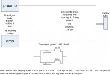
So to answer your question, you have created a frequency dependent current centroid path. It will depend on the shield loop resistance, the resistances proportionality, and how the test device handles the distinction between current flowing through the shield, and current flowing through the chassis. You have no control over the frequency break points in switching from cable to cable.
As I recall, you also mentioned that you used a capacitor shunt to ground at the output jack to reduce the harmonics through the test cable, where did that current go and how did the equipment handle it?
ps..I've added a simplified ground loop depiction, showing how one can calculate the break frequency for the ground current. Of note is the safety ground is very heavy, and will carry a higher proportion of current at low frequencies, while at higher frequencies, it will tend to go through the IC.
j
Sorrry about that.
Here's the Q.
How does a 'ground loop' cause higher order harmonic distortion, only in a few coaxial cables, and NOT others with the SAME characteristic impedance, and 'seemingly' similar shield resistances?
Ok, the discussion has been regarding the control of current..better stated, the control of current centroids.
Given a source of signal and a load of signal connected by coax..
The only path for the signal hot is via the core of the coax. Now, how does that current return to the source?
The thinking that it's just the characteristic impedance is not accurate at such low frequencies, it makes too many assumptions which are not correct.. At audio frequencies, we MUST be aware of other paths. For unbalanced audio with safety grounded chassis, we have a big ground path the signal can return via.
Think back to the PC board example I gave. At low frequencies, that loop will be exactly that, a loop. At high frequencies, the return current will be in the ground plane, but it will follow the top trace exactly like a stripline.
Now, repeat that with a coaxial cable where both bnc's are tied to the exact same wall of a chassis. At dc, the return current is via the chassis wall, and the signal is in the core of the coax.. There is a magnetic field through the coax loop, and a hall probe style clamp-on current meter will say that there is current flowing through the coax. At high frequency, the return current will be via the shield, and the hall probe will say zero. At low frequencies, you could make a loop of wire and tape it to the coax, and you will create an air core transformer, it will pickup low frequency signal. As you raise the signal frequency, the loop will pick up less and less as the shield current rises.
Now, let's reverse stimulus/response. If you have an external time varying magnetic field that couples to that coax loop, what happens?
At low frequency, the loop inductance including the chassis jack to jack path is high but the reactance is low, so an external stimulus will couple to the core wire and shield, but the shield wire cannot fully cancel the field because of it's resistivity as well as that of the chassis, connectors, and contact resistances.. At high frequency, the loop inductance is too high to support loop current via the chassis, so the coax is more effective at shielding, not needing the unbalanced shield current to buck the trapped flux in the loop. (I lament the discontinuation of IEEE-1050)
So to answer your question, you have created a frequency dependent current centroid path. It will depend on the shield loop resistance, the resistances proportionality, and how the test device handles the distinction between current flowing through the shield, and current flowing through the chassis. You have no control over the frequency break points in switching from cable to cable.
As I recall, you also mentioned that you used a capacitor shunt to ground at the output jack to reduce the harmonics through the test cable, where did that current go and how did the equipment handle it?
ps..I've added a simplified ground loop depiction, showing how one can calculate the break frequency for the ground current. Of note is the safety ground is very heavy, and will carry a higher proportion of current at low frequencies, while at higher frequencies, it will tend to go through the IC.
j
Attachments
Last edited:
Guys we have been through this before. If you look hard enough all things distort. The hard to believe issue is can one actually hear a distortion product that is 120 to 160 db below peak signal level?
Now as mentioned my current interest is looking at the possibility that there is another mechanism that allows these low level distortions to under certain conditions and for brief periods of time rise to a much higher level that certain trained listeners can then identify.
On another thread it was mentioned that using square waves makes it quite do-able for determining DSP vs. analog. Now the side issue is of course how close can you get to square waves in any recorded music format?
Now there is considerable interest in a precise and repeatable demonstration of some of these "Magic" claims.
But let me claim that if you stand in a field on top of a hill so you are the highest point for miles that doing so during a thunderstorm is a very bad idea. What protocol for testing this would convince a true skeptic? How many repetitions of that demonstration would be required?
Maybe. Testing anything at high frequncy and low impedance is NOT easy. Many have been led down the garden path by not understanding where the current goes, and even where the centroids are.John (N) We cross posted. Yes that is one mechanism, there may be others!
j
While I agree that the Sound Tech is not the last word in measuring distortion phenomena it does have a balanced input which will reduce the the return currents through the chassis.
I have the same nagging feeling when I am measuring something, that I am getting bad info because its never as simple as it looks.
I have the same nagging feeling when I am measuring something, that I am getting bad info because its never as simple as it looks.
But let me claim that if you stand in a field on top of a hill so you are the highest point for miles that doing so during a thunderstorm is a very bad idea. What protocol for testing this would convince a true skeptic? How many repetitions of that demonstration would be required?
A map of lightning strike patterns. If one is particularly skeptical, the map can be given to the claimant without any topographical reference, and the claimant can show which areas are statistically more likely to be hit. If those correspond to the hilltops, QED.
Now as mentioned my current interest is looking at the possibility that there is another mechanism that allows these low level distortions to under certain conditions and for brief periods of time rise to a much higher level that certain trained listeners can then identify.
Heh heh...don't get me started.
4 quadrant operation, control of positive and negative rail currents, internal chassis magfields caused by rail current centroids not being coincident..feedback loop coupling to magfield quadrant dependent...
Ed, we may need to talk. I have some stuff I worked on in may of 2004 that may interest you. I'd try to not be so polysyllabic....promise..😉
j
While I agree that the Sound Tech is not the last word in measuring distortion phenomena it does have a balanced input which will reduce the the return currents through the chassis.
I have the same nagging feeling when I am measuring something, that I am getting bad info because its never as simple as it looks.
sigh..when I get results which match expectations, I clearly did something wrong..
j
- Status
- Not open for further replies.
- Home
- Member Areas
- The Lounge
- John Curl's Blowtorch preamplifier part II