Two of my friends have just finished the JC-3 power amplifier use the pcbs I sent them. They have very good comments for it.
The devil is in the details
I was hoping JC would say "that's an old design, Try this one", but he is to smart for me. At least I tried.
I was hoping JC would say "that's an old design, Try this one", but he is to smart for me. At least I tried.
My friend uses 0.1 Ohm as emitter resistors for power transistors as specified on original JC-3 schematic but he found once he adjusted the bias of output stage at 500ma, the current is keep going up constantly. Would anyone can tell why this happen and any solution?
Thank you.
Thank you.
maybe needs bigger heatsinks.
Cordel posted a formula that showed that as Vce goes up the value of Re must also go up to maintain thermal stability.
Try looking in Cordel's interviews.
Cordel posted a formula that showed that as Vce goes up the value of Re must also go up to maintain thermal stability.
Try looking in Cordel's interviews.
AndrewT said:maybe needs bigger heatsinks.
Cordel posted a formula that showed that as Vce goes up the value of Re must also go up to maintain thermal stability.
Try looking in Cordel's interviews.
Hi Andrew
That could be the possibility. I will search Cordel's interviews and on the other hand tell my friend to use bigger heatsinks. Let's wait to see the result.
Thanks
AndrewT said:maybe needs bigger heatsinks.
Cordel posted a formula that showed that as Vce goes up the value of Re must also go up to maintain thermal stability.
Try looking in Cordel's interviews.
I do not understand thsi Vce and Re interraction.
A first idea would be to check the correct tracking of the Vbias cicuit.
Also using a Re of 0.22 with the correct bias will help.
JPV
i agree with andrew t.
if you are building as close to the original as you can, remember these were full class a power amps. in class a, there is no such thing as too much heat sink.
mlloyd1
if you are building as close to the original as you can, remember these were full class a power amps. in class a, there is no such thing as too much heat sink.
mlloyd1
AndrewT said:maybe needs bigger heatsinks.
...
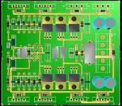
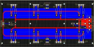
Maybe in this case the smaller PCB size is not an advantage.
To having good heat sinking it would help the power transistors to have some distance between them.
To having good heat sinking it would help the power transistors to have some distance between them.
After 2 years exploration, I finally completed my ultimate JC-2 pre-amp.
Now I want a power amplifier to hook with the JC-2. I am now currently using Nelson Pass A40 so the new power amp must also be a class A amp. JC-3 is my first choice.
Base on the original circuit, I added 2 more pairs output transistors plus a power supply for the front end stage. Schematic attached, comments are welcome.
Attachments
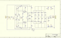
i made some simulations of this amp, a classic complemantary differential,
and it s more than instable...as little as 1 nF capaciatance in paralel with
a 8R load make it oscillate...increasing the compensation to 47 pf did make nothing..
the problem is that OLG is too high, with no degeneration in the sources
of the input differentials...surely, with some little effort, it can be stabilized,
but at the expense of distorsion rate, wich, despite being very low is no
better than that of the same topology using BJTs at the input...
hope that no one did implemented it in this lacking version....
i m stunned at the fact that proved designers didn t care about this,
apart from Pavel Macura who pointed instabilty issues...
i will later simulate Macura s improved version and publish it in the relevant
thread...
regards,
wahab..
i made some simulations of this amp, a classic complemantary differential,
and it s more than instable...as little as 1 nF capaciatance in paralel with
a 8R load make it oscillate...increasing the compensation to 47 pf did make nothing..
the problem is that OLG is too high, with no degeneration in the sources
of the input differentials...surely, with some little effort, it can be stabilized,
but at the expense of distorsion rate, wich, despite being very low is no
better than that of the same topology using BJTs at the input...
hope that no one did implemented it in this lacking version....
i m stunned at the fact that proved designers didn t care about this,
apart from Pavel Macura who pointed instabilty issues...
i will later simulate Macura s improved version and publish it in the relevant
thread...
regards,
wahab..
Hi wahab
You need to adjust the value of the small cap C11 in my schematic in the feedback network to make the amp stable.
Hi wahab
You need to adjust the value of the small cap C11 in my schematic in the feedback network to make the amp stable.
hi, hkc,
it s rather C12 , C11 being the zobel net. cap..
well, i did trim the value, and also increase the lag
compensation, but it had no great effects...
also, i did not use a LC circuit at the output, as
i consider that amps must be stable without this kind of
trick, at least for low values of capacitance loading...
i also did check pavel s improvement of this design ,
which is fairly more complexe, and it worked very well,
as it needed only very minor adjustements, surely because
i used different devices for the EF power stage..
by the way, can you tell me which simulator you re using?
best regards,
wahab
Hi wahab
I did not simulate but some of my buddies built this amp let's say 4~5 people and all they gave very positive sounding comments on it.
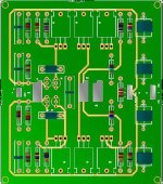
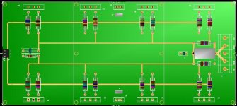
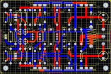
Hi HCK, by the way, his name is Sigurd Ruskowski. Can your tracks handle the current, or do you have wide tracks below the board. Also the hole sizes on the power transistors differ and I think the pads are too small, there is quite a lot of mechanical stress bolting the transistors down.
Hi HCK, by the way, his name is Sigurd Ruskowski. Can your tracks handle the current, or do you have wide tracks below the board. Also the hole sizes on the power transistors differ and I think the pads are too small, there is quite a lot of mechanical stress bolting the transistors down.
Hi Ras
Thank you for your comment, I will widen the tracks and use bigger size pads and will send revised pcb layout soon.
PS. Thanks for correcting me about Ruskowski.
- Home
- Amplifiers
- Solid State
- John Curl amp