Yesterday, before installing the new custom throat adaptor, I started measuring waterfalls at the horn mouth when using the "composite" adaptor I have been listening to for weeks. Surprise! Look at this resonance at 980 Hz .

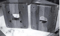
This "composite" adaptor is a mating of two off-the-shelf aluminum pieces:
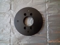
1. The Eminence HA14-2 conical adaptor that enlarges the 1.4" driver exit to a 2" diameter circular surface area (right).
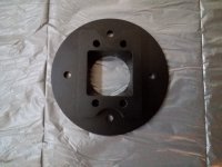
2. The TAD TH-4001 adaptor that accepts a 50 mm circular and outputs a 40 x 50 mm rectangular surface area matching the entrance of the TH-4001 wooden horn (left).

The HA14-2 looks like this:

The TAD TH-4001 adaptor likes this:


Note the negative flare on the vertical axis. The entrance measures 50 mm high and the exit 40 mm high. The net surface area expansion is zero over the 2 cm length.
Could it be that this negative flare creates a quarterwave resonator? The distance between the flare and the diaghragm is about 9.6 cm. This 9.6 cm is a quarter wavelength of the resonance frequency (890 Hz).

Gurus, does this make sense or do you see other explanations?
This "composite" adaptor is a mating of two off-the-shelf aluminum pieces:
1. The Eminence HA14-2 conical adaptor that enlarges the 1.4" driver exit to a 2" diameter circular surface area (right).
2. The TAD TH-4001 adaptor that accepts a 50 mm circular and outputs a 40 x 50 mm rectangular surface area matching the entrance of the TH-4001 wooden horn (left).
The HA14-2 looks like this:
The TAD TH-4001 adaptor likes this:
Note the negative flare on the vertical axis. The entrance measures 50 mm high and the exit 40 mm high. The net surface area expansion is zero over the 2 cm length.
Could it be that this negative flare creates a quarterwave resonator? The distance between the flare and the diaghragm is about 9.6 cm. This 9.6 cm is a quarter wavelength of the resonance frequency (890 Hz).
Gurus, does this make sense or do you see other explanations?

I'm no expert, but your explanation sounds plausible. I guess we need to wait for docali and allenb to weigh in? Thank you for sharing, because at the very least this indicates that combining these adapters might be not be as benign as expected?
Indeed, I was not expecting this. Perhaps worth adding that I checked diaphragm alignment in the driver (it is well aligned). Also the resonance occurs whether I measure outside or inside the horn, on axis or slightly off axis, and irrespective of signal level (54 dB to 104 dB SPL).
Why not measure the driver without the horn? At least it will show if the driver is faulty or not...
Much of this is speculation but your explanation above is plausible. It may figure more than the local wall shaping concern at this wavelength, but both have to be considered in an adapter design.The net surface area expansion is zero over the 2 cm length.
Looking forward to seeing the result with the new adapter.
The adapters that came with my Athos Yuichi A290 clones appear to be the same as yours. I believe its a generic adapter alot of guys use since it's readily available.Yesterday, before installing the new custom throat adaptor, I started measuring waterfalls at the horn mouth when using the "composite" adaptor I have been listening to for weeks. Surprise! Look at this resonance at 980 Hz .
The TAD TH-4001 adaptor likes this:
View attachment 1154305
View attachment 1154306
Note the negative flare on the vertical axis. The entrance measures 50 mm high and the exit 40 mm high. The net surface area expansion is zero over the 2 cm length.
Could it be that this negative flare creates a quarterwave resonator? The distance between the flare and the diaghragm is about 9.6 cm. This 9.6 cm is a quarter wavelength of the resonance frequency (890 Hz).
The horizontal entrance into the horn has a sharp transition angle that doesn't look like it will perform well without some modification to smooth out the entrance angle. I did some quick RTA testing which show resonances in the same 1k area as you observe. This is using B&C DCX50 2" coax drivers, which have performed very well on large 300 hz cutoff bi-radial horns, so i know the drivers are capable of decent SQ.
Needless to say, I'm not impressed Athos used this adapter considering the way their A290 clone are machined at the throat entrance. Both the horn throat and adapter will need considerable blending work to perform well. This finding has stalled the progress on my build and really disappointed me considering the price I paid.
I'll try to post some pics soon.
I have Athos Yuichi A-290, and the interface adaptor to the horn is 5cm x 5cm (square) as expected. The TH-4001 uses a different adaptor from what I am told, and can see from the photographs. Athos told me specifically that these adapters are custom made for them. I am sure there are lots of similar ones out there.
I will try to dig up a picture that hopefully shows this clearly. I can also post a waterfall plot on axis of one of my TD-4001 on A-290 when I have a little more time.
I will try to dig up a picture that hopefully shows this clearly. I can also post a waterfall plot on axis of one of my TD-4001 on A-290 when I have a little more time.
Yesterday, before installing the new custom throat adaptor, I started measuring waterfalls at the horn mouth when using the "composite" adaptor I have been listening to for weeks. Surprise! Look at this resonance at 980 Hz .
View attachment 1154303
Could it be that this negative flare creates a quarterwave resonator? The distance between the flare and the diaghragm is about 9.6 cm. This 9.6 cm is a quarter wavelength of the resonance frequency (890 Hz).
Many variables in your setup. A driver, two adapters, a horn. A quite long event in the time domain is looking more like a material resonance to me but I have to admin that also the inner adapter shapes do not look optimal. It would be interesting so see a similar waterfall with the driver attached to jmlc horn. The you could at least sort out the driver.
Thank you all for you comments and suggestions. I will do some more measurements of this driver unit this weekend and will post results here. And as I have built some confidence, will test the unit without horn too.
My spacer opening goes from 50mm driver opening to 50 x 50mm horn throat and is 23mm thick.
Not sure if this is the original spec for a 2" TAD driver mated to a Yuichi A290.
The corners aren't radiused on the horn throat as they are on the adapter. This can't be good for SQ and will cause reflections inside the horn.
The one thing for sure is the horizontal plain goes from no flare to a sudden sharp 40 degree turn. It will need some blending but the question is how much and at what angle to radius it.
Attachments
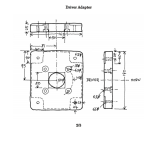
50mm round to 50mm square over 25mm was the original spec to match the TD4001. The point is to match the surface areas while respecting the expansion profile. Snips of the original attached.Not sure if this is the original spec for a 2" TAD driver mated to a Yuichi A290.
Fin horns don't behave in an easy way to intuit. The square entrance does not cause any undue problems in simulation. If the areas and expansion are correct there is a smooth 3D expansion to the wavefront without any abrupt change despite what it might look like.The corners aren't radiused on the horn throat as they are on the adapter. This can't be good for SQ and will cause reflections inside the horn.
The one thing for sure is the horizontal plain goes from no flare to a sudden sharp 40 degree turn. It will need some blending but the question is how much and at what angle to radius it.
Of course there are other ways to make similar horns without fins that have a smooth transition from mouth the throat, but without the fins, something else is needed to fill that function of widening the HF when using a 2" driver, if that is a goal.
Attachments
Not sure if this helps or not. This is one of those adapters on one of my A-290 horns. As best I can ascertain the adapter is a good fascimile of what Yuichi described in his drawings.

Thanks for all the replies guys. I appreciate all the info.
It appears the sharp horizontal turn (see marking in pic below) could be a diffraction point to guide the wavefront into the finned area for adequate expansion into the flare. I'm not sure if that's what the designer intended, but it looks like a weak point in the design. I suppose it would be smart to look at the original drawing for info on the flare rate at the throat. My DCX50s have a fairly rapid expansion in the throat but there are parts of the phase plug which turn somewhat along with the walls of the driver's throat to net a more subtle expansion. I'm definitely aware of the 3d aspect which can mess with your head in terms of visualizing the whole thing. I just know sharp turns are not good for smooth FR.
Anyone have info on the original design's expansion rate?
Attachments

Last edited:
Since we last talked I acquired a pair of TAD-4001 drivers for my Yuichi A-290. The results with the A-290 were not entirely satisfactory with the Radian NEO950PB drivers due to the driver exit angle as far as I and several smart advisors could figure out.. Much happier with an old pair of JBL2440 equipped with 2441 diaphragms, but I found the distortion performance left something to be desired. The TADs match the distortion performance of the Radian, and have much flatter frequency response. The 4001 is significantly better in most respects than either of my other drivers and is a good match on this horn whereas the Radian wasn't. The JBL and TAD drivers apparently have exit angles in the 8 -10° range and the Radian is 21°
FWIW and note my very limited experience but these are the best sounding mid-range horns I have owned, but really seem to need very specific drivers. Yuichi recommended the TD-4001, JBL2441, and later the JBL2450 (not SL). I have heard from other people on diyA that the 2450 with Be diaphragms can sound quite good on the A-290 and TH-4001 horns, but really isn't going to cost a whole lot less than the TD-4001 once you factor in the Be diaphragms.
FWIW and note my very limited experience but these are the best sounding mid-range horns I have owned, but really seem to need very specific drivers. Yuichi recommended the TD-4001, JBL2441, and later the JBL2450 (not SL). I have heard from other people on diyA that the 2450 with Be diaphragms can sound quite good on the A-290 and TH-4001 horns, but really isn't going to cost a whole lot less than the TD-4001 once you factor in the Be diaphragms.
Last edited:
@kevinkr - Thanks for checking all that out for me. I thought the adapters were the same on all the A290s, but I guess its not the case after all.
My budget won't support TAD 4001s. I mainly wanted to avoid running a super tweeter, so I chose the DCX50 after hearing its close DCM50 sibling on other biracial horns, which i loved. The paper/CF diaphragm used on both the mentioned B&Cs is very smooth and extends down further than most other large drivers I've heard, including the AXI2050. The only difference in both B&Cs is the DCX50 has a super tweeter element built in, making it a coax. Most 2" drivers dont extend that far up, so a separate tweeter is needed. If the HF is still insufficient even with the DCX50, I can always add a super tweeter afterwards but hopefully I won't need it. Most decent 2" drivers run a shallower exit angle anyways, so mating to the A290s shouldn't be that much of an issue.
That sharp angle is really what bothers me most. I know it can't be good to have that if there's no vertical expansion taking place in the finned area once the wavefromt reaches the finned entrance way. I'm trying to look up the original A290 plans and determine whether this sharp turn is intended by the designer. Can't imagine a diffraction angle is wanted in this horn's design, but i want to get the facts first before i apply judicial use of the die grinder.
@kevinkr - PS... make sure your adapter screws are all tighted down on your adapters. Only 2 of the 4 screws were fully tightened down onto the adapter flange. Its hard to verify this due to how tight the 4 threads were cut into the horns. I was worried the threads would snap during the adapter removal Thats why I want to install threaded machine screw inserts on mine when I can get around to it.
TAD-4001 on Yuichi A-290 clone, no EQ, amplifier source impedance 1.8 ohms, Umik-2, 7.5cm (approx) from horn mouth.

There is something going on at ~4.5kHz on both channels which I need to identify, this is true regardless of driver fitted, and appears to disappear if I flip phase in the DSP XO which being based on a highly modified DCX2496 might be the culprit. I have also had ongoing problems with instability (very low level tones) in the driver stages of the power amps. It might be something totally unrelated. The system is active with six channels of amplification, two powered subs, digital XO (2496) and MiniDSP SHD. (I use Dirac3) still working out the kinks here and there.

This is THD relative to the fundamental

There is something going on at ~4.5kHz on both channels which I need to identify, this is true regardless of driver fitted, and appears to disappear if I flip phase in the DSP XO which being based on a highly modified DCX2496 might be the culprit. I have also had ongoing problems with instability (very low level tones) in the driver stages of the power amps. It might be something totally unrelated. The system is active with six channels of amplification, two powered subs, digital XO (2496) and MiniDSP SHD. (I use Dirac3) still working out the kinks here and there.
This is THD relative to the fundamental
Last edited:
- Home
- Loudspeakers
- Multi-Way
- JMLC and Yuichi horns measurements