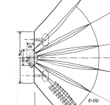
There is no sharp angle. Maybe this explanation will make more sense to you. A fin horn is a form of a multicell, look down on the part I snipped from Yuichi's document. The fins are arranged on a radius. I have attached a hand drawing by @docali that I hope he won't mind me sharing. The origin point relative to the entrance size determines the radius. The wavefront that emerges from the conical exit and round to square adapter becomes somewhat cylindrical (as the vertical is constrained as it enters the horn), but looking down it is expanding. When this expansion matches the radius there is no discontinuity at the junction, the portion of the wavefront enters the cell and continues to expand along it and if the cells have been designed correctly the separate wavefronts combine back together nicely at the exit like a phase plug.That sharp angle is really what bothers me most. I know it can't be good to have that if there's no vertical expansion taking place in the finned area once the wavefromt reaches the finned entrance way. I'm trying to look up the original A290 plans and determine whether this sharp turn is intended by the designer. Can't imagine a diffraction angle is wanted in this horn's design, but i want to get the facts first before i apply judicial use of the die grinder.
Attachments

@profiguy has a point.
It won't though. Radial will by definition have a point apex in this plane, as Docali has shown. This requires a small source. A finite plane source will require diffraction to become spherical.When this expansion matches the radius
That the throat on these horns are relieing on diffraction seems quite obvious to me and that is one part I would like to "correct" by using an oswg profile in horizontal plane. Starting with a plane wave and "pull" it out to meet the fins. It will probably beam a bit more but suffer less from abrupt discontinuities.
//Anders
//Anders
I closely looked over the drawings Kevin posted and tried to visualize the function of the small volume of space right before the fins. it looks like that sharp corner entry angle is a necessary evil to develope a congruent (widely radiused) wavefront into the later part of the throat right before the fins come into play. Perhaps Yuichi left out a small radius so as to not further complicate the build - not sure. I realize this may be a minute little detail to most, but it can have a rather positive impact on performance higher up in FR depending on the driver used. I may build 2 wooden adapter plates and play around with different shapes going into the secondary throat opening.
This may explain why horns like Klipsh's k402 don't require a perfect driver opening transition to the throat (abrupt transition from round to square shape). I'm just trying to understand why the source wouldn't start at the driver phase plug ending and not the horn entry point after the driver, as any lack of expansion rate in the transistion between the two would cause reflections.There is no sharp angle. Maybe this explanation will make more sense to you. A fin horn is a form of a multicell, look down on the part I snipped from Yuichi's document. The fins are arranged on a radius. I have attached a hand drawing by @docali that I hope he won't mind me sharing. The origin point relative to the entrance size determines the radius. The wavefront that emerges from the conical exit and round to square adapter becomes somewhat cylindrical (as the vertical is constrained as it enters the horn), but looking down it is expanding. When this expansion matches the radius there is no discontinuity at the junction, the portion of the wavefront enters the cell and continues to expand along it and if the cells have been designed correctly the separate wavefronts combine back together nicely at the exit like a phase plug.
Those of us learning to use REW for waterfall analysis of drivers will have noticed that the default REW settings are for showing room modes (time span 300 ms). To analyse drivers (time span 4 to 8 ms) I found the REW settings in this example to be most useful:
REW waterfall vs Amir's speaker measurement waterfall
And here is a screen shot:

In my earlier shot I used Time Range 5 ms, and ticked OFF "Use CSD Mode" to maintain frequency fidelity.
REW waterfall vs Amir's speaker measurement waterfall
And here is a screen shot:
In my earlier shot I used Time Range 5 ms, and ticked OFF "Use CSD Mode" to maintain frequency fidelity.
Kevinkr, profiguy and fluid - Thank you for the photos, measurements and discussion of surface expansion and the importance (or not) of avoiding abrupt changes in wall angles. Some answers bring up more questions. I debated on this very same matter with docali over the last couple weeks, and the custom throat adaptor #1 that I am about to test is a compromise. The flare rate is set aside for a short length near the exit to smooth out the wall transition to the horn throat. I have not yet settled on the final shape. Remember this is for a 1.4 inch driver.
Custom adaptor 1:


Custom adaptor 1:
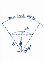
Hi, this sketch was only to show how these horns are constructed. A point source is assumed what is of course not true for a real driver. So wfrstp is the construction wave front.There is no sharp angle. Maybe this explanation will make more sense to you. A fin horn is a form of a multicell, look down on the part I snipped from Yuichi's document. The fins are arranged on a radius. I have attached a hand drawing by @docali that I hope he won't mind me sharing. The origin point relative to the entrance size determines the radius. The wavefront that emerges from the conical exit and round to square adapter becomes somewhat cylindrical (as the vertical is constrained as it enters the horn), but looking down it is expanding. When this expansion matches the radius there is no discontinuity at the junction, the portion of the wavefront enters the cell and continues to expand along it and if the cells have been designed correctly the separate wavefronts combine back together nicely at the exit like a phase plug.
And that was the only meaning I attached to it, not Allen's interpretation of my words.Hi, this sketch was only to show how these horns are constructed.
The wavefront shape at the end of the long conical adapter in the TD4001 and then through the round to square adapter will not be plane even assuming it actually was at the end of the phase plug. My point (as it seems it was not well explained) is that there will be curvature as it enters the square section and the closer that curvature matches the radius of the fins the less disturbance there will be.
Kolbrek "By logical reasoning, the assumption that the wave-fronts in a horn are plane cannot be true. If it was so, the speed of sound along the horn walls would need to be greater than the speed of sound along the axis. This cannot be the case, and the result is that the wave-front on the axis must gain on that at the horn walls, so the wave-fronts will define convex surfaces"
Here are waterfall measurements of the same serial number Radian 745BE 1.4" driver without any filtering.
Naked driver, measured at driver exit:

On AH425 (JMLC) horn, close to horn mouth:

On TH-4001 through off-the-shelf composite adaptor described earlier in thread, close to horn mouth:

On TH-4001 through custom near constant flare PETG adaptor, close to horn mouth:

Naked driver, measured at driver exit:
On AH425 (JMLC) horn, close to horn mouth:
On TH-4001 through off-the-shelf composite adaptor described earlier in thread, close to horn mouth:
On TH-4001 through custom near constant flare PETG adaptor, close to horn mouth:
Now repeating my very first waterfall plot showing the 890 Hz issue which was with EQ, on TH-4001 through the off-the-shelf composite adaptor described earlier in thread.

Repeat measurement angled like the plots in the post above to make comparisons easier. Floor is raised 5 dB to help identify the worst offenders.

And the same driver, horn, and EQ filter but now through the PETG Custom Adaptor #1:

Note that the above seven waterfalls are all on a 5 ms time range.
Repeat measurement angled like the plots in the post above to make comparisons easier. Floor is raised 5 dB to help identify the worst offenders.
And the same driver, horn, and EQ filter but now through the PETG Custom Adaptor #1:
Note that the above seven waterfalls are all on a 5 ms time range.
Last edited:
Hi Pierre, Can you add the original measurement to the post above? Makes direct comparison easier.
I am going to try to get a similar capture of the TD-4001 on the Yuichi, as soon as tomorrow hopefully.
Interesting results, I would need to compare to some other horns and drivers to get a good frame of reference, since this is all new to me, but none of these look bad IMO at first inspection.
I am going to try to get a similar capture of the TD-4001 on the Yuichi, as soon as tomorrow hopefully.
Interesting results, I would need to compare to some other horns and drivers to get a good frame of reference, since this is all new to me, but none of these look bad IMO at first inspection.
I edited the post like you asked (I think). Yes, the driver is working fine and I am satisfied with the overall transient response. There are a couple of funny things happening just below 1 kHz and around 2 kHz on the TH-4001 (not on the AH425) that warrant investigation. Also, the PETG custom adaptor design #1 does measure better in the time domain than the composite one. Here's what it looks like:

Yes, measurements of TD-4001 on the Yuichi would be terrific. Let's share!
Yes, measurements of TD-4001 on the Yuichi would be terrific. Let's share!
Last edited:
So this is what I got... Topping DAC / Laptop does not appear to be functioning correctly so this acquisition is questionable. I narrowly avoided a catastrophic outcome with this measurement. (Shattered diaphragm, loud clacks are a cause for concern.) Win 11 does not play nicely with some of my measurement hardware and I had both problems with system sound and sweep quality. Do it indirectly through the SHD and DCX are much safer and give similar results in most cases.
This capture was before the "incident"

This capture was before the "incident"
Last edited:
So some good news.. The diaphragm is not damaged.
Distortion measurement 600Hz - 12kHz

I think you can see one of the reasons why I really like the TD-4001 in the distortion plot below

This is through the system electronics, and I did not disable the XO, which I can do safely in this configuration. So I will try again at some point. This measurement is restricted to 600Hz - 12kHx which is the operating range of the horn and driver.

Distortion measurement 600Hz - 12kHz
I think you can see one of the reasons why I really like the TD-4001 in the distortion plot below
This is through the system electronics, and I did not disable the XO, which I can do safely in this configuration. So I will try again at some point. This measurement is restricted to 600Hz - 12kHx which is the operating range of the horn and driver.
Last edited:
Kevin, thank you and glad to read that your diaphragm survived! Phew…
The waterfalls show how nice a driver the TD4001 is. (It is the gold standard in my book.)
Please could you show us the same plots after disabling CSD? This will improve the resolution in the midrange frequencies.
Driver distortion is proportional to level. I test mine using 1 to 2 Vrms when it is mounted on a horn and 100mV when it is naked. What level did you use in your measurements? At what distance from the horn mouth did you measure?
OSWG uses diffraction too 😉That the throat on these horns are relieing on diffraction seems quite obvious to me and that is one part I would like to "correct" by using an oswg profile in horizontal plane. Starting with a plane wave and "pull" it out to meet the fins. It will probably beam a bit more but suffer less from abrupt discontinuities.
//Anders
The measurement was done on axis, pop screen on (not usually the case) centered and flush with the edge of the horn mouth. I am not convinced room sound is not getting back to the horn, but the short measurement window should help with that?Kevin, thank you and glad to read that your diaphragm survived! Phew…
The waterfalls show how nice a driver the TD4001 is. (It is the gold standard in my book.)
Please could you show us the same plots after disabling CSD? This will improve the resolution in the midrange frequencies.
Driver distortion is proportional to level. I test mine using 1 to 2 Vrms when it is mounted on a horn and 100mV when it is naked. What level did you use in your measurements? At what distance from the horn mouth did you measure?
I do my measurements at specific Spl levels rather than specific power levels and my typical range is 70 - 100dBspl at the mouth of the horn which is reflective of typical use conditions in my moderately sized listening/lab space. I would estimate at 90dBspl that average power levels are significantly less than 100mW. My power amplifiers are 6.5W 0fdbk 300B SE amps of my own design driving the mids and tweeters, and spend almost all of their time below 1W.
This is the same one as above without CSD.
No CSD
With CSD for comparison.
Thank you Kevin. Without CSD your plot shows better what is really happening below 3 kHz, especially near 3-4 ms.
Although I am just beginning to decode what to read off these plots, I find it interesting (and in a sense reassuring) that our measurements show similarity in many regions considering we are using drivers of different diaphragm and exit sizes, as well as different horns. What our configurations have in common is a sectoral, finned horn configuration having a rectangular/square entrance.
Your measuring at lower levels than I do helped me understand the extremely low distortion exhibited by the driver. Thank you.
Lastly, you are right that when using such short windows the room is effectively removed from the measurement. When measuring the JMLC I simply put it on the driver resting on its back on a blanket on the floor, pointing up to the ceiling. Upon increasing the window duration it became very obvious when the ceiling reflection was received: it looked like a vertical wall at X ms on the waterfall plot! Since we measure the sectoral horns projecting horizontally and position the mic close to the mouth, the wall reflections are delayed passed the waterfall windows. Now what about ceiling and floor reflections? The vertical dispersion of the sectoral is fairly low, so I don't think this is much of an issue either. Experts may chime in!
- Home
- Loudspeakers
- Multi-Way
- JMLC and Yuichi horns measurements