Ian,
I know those pages. If you look for the missing pieces of your JLH collection, you find Paul´s pages.
I suspect JLH published much more articles, and it is a shame that those things are lost or at least not publically available. But then - this was way before anybody thought of archiving. In fact some of it was earlier than the days Jimi died.
-helmut
They are archived in your Library.
That's the way we did our research in the old days. We went looking for the information.
The National Library of Scotland archives EVERY publication printed in Scotland.
I expect you have similar.
That's the way we did our research in the old days. We went looking for the information.
The National Library of Scotland archives EVERY publication printed in Scotland.
I expect you have similar.
Ian,
I know those pages. If you look for the missing pieces of your JLH collection, you find Paul´s pages.
I suspect JLH published much more articles, and it is a shame that those things are lost or at least not publically available. But then - this was way before anybody thought of archiving. In fact some of it was earlier than the days Jimi died.
-helmut
I have a several of Linsley-Hood's articles. Much of what is available from internet sources is condensed in form, omitting such as printed circuit board layouts, and Hood's insights into aspects of audio design. That said there is some good information on Geoff Moss' site "The Class A Amplifier Site" now hosted by Rod Elliott's Sound Pages - The 1969 Class A amplifier see The Class-A Amplifier Site.
You can also find there the Class AB amplifier Hood developed from that - see The Class-A Amplifier Site - JLH Class-AB Amplifier.
At first glance the Class AB amplifier looks too antiquated in comparison to the sleek operational amplifier based designs such as the Classic JBL T-Circuit devised by Bart Locanthi - the output stage of which has a widespread following under the name of EF3 on this site and which has been adopted commercially for a good many high power amplifier designs. This is often presented to most observers as a simple recipe which works - period. That is what most people seem to want today.
Hood thought Class AB design had some way to go in 1970 and discussed the difficulties inherent in design arising from the use of bipolar output stages. He covered the subject in sufficient detail for the average enthusiast to understand and confronting the Hi-Fi establishment in Britain in the process - there is much information in Hood's replies to " Letters to the Editor" [Wireless World] which included Peter Walker of Quad.
We might have better power devices available today but the physics are unchanged. We still have people selling or building Class A amplifiers so the questioning mind would have to ask why is that so.
I recommend that people read these articles for the understanding they convey and as examples of Hood's earnest efforts to inform.
In this last regard I am happy to scan material and post or email.
Last edited:
They are archived in your Library.
That's the way we did our research in the old days. We went looking for the information.
The National Library of Scotland archives EVERY publication printed in Scotland.
I expect you have similar.
In New Zealand I would expect our National Library to do likewise however it would be very costly to subscribe to every overseas periodical and one would be more likely to find them in the stacks of the main libraries in the major cities or technical departments of universities and institutes.
I believe that Amazon and the internet have diminished the availability of technical publications in main municipal libraries. Where I live one has to go to the Central City area of Wellington 30 km away. Now I am retired I hate going into larger cities and don't go there unless it is for some hospital appointment.
There is a local library where I live but no regional library service as existed in Auckland where I lived up until 2002. The Upper Hutt library has no subscription to any electronic periodical and has ceased subscribing to Hi-Fi News and Gramophone. How" Kulchered" is that?
Last edited:
Hmm. I must one day do a library article search (when I have this amp off my back🙄). But honestly, I don´t expect much from this.
One could think about an online knowledge base in times of computers. Any idea of the legal aspect of this? Some of the articles used to be payed reprints.
-helmut
One could think about an online knowledge base in times of computers. Any idea of the legal aspect of this? Some of the articles used to be payed reprints.
-helmut
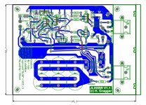
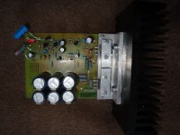
The new layout is done, etched, populated - and working.
(note the flying pots are replaced by proper top-adjust 25 turn pots once they arrive). In short - the oscillation in the prototype was due to bad layout.
I have given my best to incorporate state-of-the-art techniques for mixed signal circuits. Long live the Analog Design Seminar Manual.
As suggested, I have adhered to the JLH layout suggestion, except that JLH mounted the output devices with cables, me directly on the PCB.
I have taken less care of beautiful optics, but taken extreme care for return currents and ground management. The absence of parallel lines and sharp trace edges lead to a vintage looking routing.
The board is thus no longer as compact as I wished it to be😱 but it works
All power connections are to the bottom right, output devices are screened with a ground plane. Board decoupling is as close to the power pins as possible. All grounds meet at one single star ground point. Screen areas thus cannot pollute sensitive areas.
Most sensitive circuit parts (input) are to the upper left, far away from the output, all connected with comparably beefy power tracks.
Small signal parts are separated with a ground plane that ultimatively meets at the star ground point.
Mosfet drive signals are guarded with a ground plane where possible. A safety 100R gate stopper is located close to the mosfets (JLH does not use one in this circuit, maybe they are redundant).
All critical components (output Zobel, FB compensation network) are positioned to their final destination with short tracks.
This effort payed!
The amp runs stable at full load, just at the onset of clipping, on a sinewave, with and without cap.
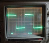
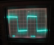
I have tested the amp with a 1kHz 40Vp-p square wave, somewhat below max to avoid clipping.
Please behold the scope traces for resistive load (8ohm shunt) and reactive load (8ohm shunt + 2.2µF cap).
Note the small overshoot with immediate settling on the rising edge and a slightly bigger one on the falling edge. This might be caused by the different drive resistors JLH mentions and may require a little more fine-tuning.
Idle current is 100mA. Interestingly, the two solder posts I have provided for adjusting idle current are useless. As soon as you open this bridge and install an ampere meter, current readings are false.
Since this is in the drain line of a mosfet there may be some oscillation introduced by the long meter cables.
However, the drive transistor current is known and idle current can comfortably be measured by inserting an amperemeter in series with the supply.
As suggested, I have not changed several variables at once and thus I have left all component values stock. I see no reason to change them now it works.
It was just later that I realized that raising the value for the reference voltage capacitor (as Bear suggested) was not a good idea, since this voltage rises just slow enough to prevent pops on switch-on.
Increasing this cap by a magnitude would change the turn-on muting to un-bear-able (pun intended) values.
I have also kept the output caps, the one JLH used (radial) were not smaller. Panasonic FC caps are good quality I read.
So what do you think folks. Any more checks I could convey?
Greetings,
-helmut
(note the flying pots are replaced by proper top-adjust 25 turn pots once they arrive). In short - the oscillation in the prototype was due to bad layout.
I have given my best to incorporate state-of-the-art techniques for mixed signal circuits. Long live the Analog Design Seminar Manual.
As suggested, I have adhered to the JLH layout suggestion, except that JLH mounted the output devices with cables, me directly on the PCB.
I have taken less care of beautiful optics, but taken extreme care for return currents and ground management. The absence of parallel lines and sharp trace edges lead to a vintage looking routing.
The board is thus no longer as compact as I wished it to be😱 but it works
All power connections are to the bottom right, output devices are screened with a ground plane. Board decoupling is as close to the power pins as possible. All grounds meet at one single star ground point. Screen areas thus cannot pollute sensitive areas.
Most sensitive circuit parts (input) are to the upper left, far away from the output, all connected with comparably beefy power tracks.
Small signal parts are separated with a ground plane that ultimatively meets at the star ground point.
Mosfet drive signals are guarded with a ground plane where possible. A safety 100R gate stopper is located close to the mosfets (JLH does not use one in this circuit, maybe they are redundant).
All critical components (output Zobel, FB compensation network) are positioned to their final destination with short tracks.
This effort payed!
The amp runs stable at full load, just at the onset of clipping, on a sinewave, with and without cap.
I have tested the amp with a 1kHz 40Vp-p square wave, somewhat below max to avoid clipping.
Please behold the scope traces for resistive load (8ohm shunt) and reactive load (8ohm shunt + 2.2µF cap).
Note the small overshoot with immediate settling on the rising edge and a slightly bigger one on the falling edge. This might be caused by the different drive resistors JLH mentions and may require a little more fine-tuning.
Idle current is 100mA. Interestingly, the two solder posts I have provided for adjusting idle current are useless. As soon as you open this bridge and install an ampere meter, current readings are false.
Since this is in the drain line of a mosfet there may be some oscillation introduced by the long meter cables.
However, the drive transistor current is known and idle current can comfortably be measured by inserting an amperemeter in series with the supply.
As suggested, I have not changed several variables at once and thus I have left all component values stock. I see no reason to change them now it works.
It was just later that I realized that raising the value for the reference voltage capacitor (as Bear suggested) was not a good idea, since this voltage rises just slow enough to prevent pops on switch-on.
Increasing this cap by a magnitude would change the turn-on muting to un-bear-able (pun intended) values.
I have also kept the output caps, the one JLH used (radial) were not smaller. Panasonic FC caps are good quality I read.
So what do you think folks. Any more checks I could convey?
Greetings,
-helmut
Attachments
Last edited:
The new layout is done, etched, populated - and working.
(note the flying pots are replaced by proper top-adjust 25 turn pots once they arrive). In short - the oscillation in the prototype was due to bad layout.
I have given my best to incorporate state-of-the-art techniques for mixed signal circuits. Long live the Analog Design Seminar Manual.
As suggested, I have adhered to the JLH layout suggestion, except that JLH mounted the output devices with cables, me directly on the PCB.
I have taken less care of beautiful optics, but taken extreme care for return currents and ground management. The absence of parallel lines and sharp trace edges lead to a vintage looking routing.
The board is thus no longer as compact as I wished it to be😱 but it works
All power connections are to the bottom right, output devices are screened with a ground plane. Board decoupling is as close to the power pins as possible. All grounds meet at one single star ground point. Screen areas thus cannot pollute sensitive areas.
Most sensitive circuit parts (input) are to the upper left, far away from the output, all connected with comparably beefy power tracks.
Small signal parts are separated with a ground plane that ultimatively meets at the star ground point.
Mosfet drive signals are guarded with a ground plane where possible. A safety 100R gate stopper is located close to the mosfets (JLH does not use one in this circuit, maybe they are redundant).
All critical components (output Zobel, FB compensation network) are positioned to their final destination with short tracks.
This effort payed!
The amp runs stable at full load, just at the onset of clipping, on a sinewave, with and without cap.
I have tested the amp with a 1kHz 40Vp-p square wave, somewhat below max to avoid clipping.
Please behold the scope traces for resistive load (8ohm shunt) and reactive load (8ohm shunt + 2.2µF cap).
Note the small overshoot with immediate settling on the rising edge and a slightly bigger one on the falling edge. This might be caused by the different drive resistors JLH mentions and may require a little more fine-tuning.
Idle current is 100mA. Interestingly, the two solder posts I have provided for adjusting idle current are useless. As soon as you open this bridge and install an ampere meter, current readings are false.
Since this is in the drain line of a mosfet there may be some oscillation introduced by the long meter cables.
However, the drive transistor current is known and idle current can comfortably be measured by inserting an amperemeter in series with the supply.
As suggested, I have not changed several variables at once and thus I have left all component values stock. I see no reason to change them now it works.
It was just later that I realized that raising the value for the reference voltage capacitor (as Bear suggested) was not a good idea, since this voltage rises just slow enough to prevent pops on switch-on.
Increasing this cap by a magnitude would change the turn-on muting to un-bear-able (pun intended) values.
I have also kept the output caps, the one JLH used (radial) were not smaller. Panasonic FC caps are good quality I read.
So what do you think folks. Any more checks I could convey?
Greetings,
-helmut
I remember the input capacitor for this amplifier as published has a value of 100 n and there was an 18 dB per octave filter when used with the matching pre-amp. If you are not using this the input capacitor can be increased to 470 n. You might try replacing the bottom half 330 ohm stopper with 1200 ohms.
I will look that input cap business up.
The bottom resistor is 1k2. In the original schematic (where JLH first introduces mosfets) he uses this value, but in the later revised article which I uploaded, he uses 330 again with other minor changes.
Sometimes there is a lot of guesswork in those articles.
I am very happy this worked out. Thanks to everybody who helped make this possible.
-helmut
Last edited:
I will look that input cap business up.
The bottom resistor is 1k2. In the original schematic (where JLH first introduces mosfets) he uses this value, but in the later revised article which I uploaded, he uses 330 again with other minor changes.
Sometimes there is a lot of guesswork in those articles.
I am very happy this worked out. Thanks to everybody who helped make this possible.
-helmut
The 1k2 resistor performs a low pass filter function on the lower output device. The 330R stopper resistors perform a similar function but they were not present in Hood's original circuit, and so if there was a need to even the keel due to the characteristics of the lower device, so to speak, putting equal value 330R resistors close to each gate pin would restore the imbalance to some extent.
I looked at the BJT/MOSFET pair discussed by Hood in his book - this differs in the values of the resistors with R17 and R18 being reduced to 0R22 for higher power use. That required an increase the gain from TR5 and TR6 to more or less double the 1980 circuit. The values of R13 and R16 are 4K7 while R14 and R15 are 100R. To counter act the added gain around this local loop 330R stopper resistors have been added close to the gate pins.
The latter are absent in a discussion circuit in ETI magazine in 1984 where the resistor values used produced lower gain.
I hope this information might be of use with your fine tuning
mjona,
thank you for this information. I had forgotten about the books.
Yesterday I installed the amp into its dedicated place, a HQ guitar recording amplifier.
A hefty set-back, because the thing what humming and whistling. This, although the amp itself works flawlessly.
I suspect that some circuitry (preamp, send/return loop or whatever) are either badly shielded or somehow else sensitive.
Stuff like that sets me back for a day.
-helmut
mjona,
I wanted to investigate this subject a little more and flipped through both books - I did not find the subject you are mentioning. Or was it in an article reprint?
Could you specify in which book you read that and where?
thanks,
-helmut
I wanted to investigate this subject a little more and flipped through both books - I did not find the subject you are mentioning. Or was it in an article reprint?
Could you specify in which book you read that and where?
thanks,
-helmut
Finally, best to stick to one login?
Don´t understand you here.
thanks,
-helmut
Post #49
bear is referring to your use of multiple accounts which is against the rules. Item #7 HERE
Uh. I see.
I was typing that in my workplace where a colleague was logged in. I wondered about the "administrator needs to grant permission" message and realized that it was not me that was logged in. That´s the drag with public PC´s.
I deleted that one, logged in with my account and retyped it.
It slipped my attention, that the message had gone trough.
I have nothing to hide you know😛, no split personalities.
You can delete the double entry.
-helmut
That's a good enough explanation 😀 best one I've ever heard actually for multiple accounts.
I believe you 🙂 Carry on......
I believe you 🙂 Carry on......
mjona,
I wanted to investigate this subject a little more and flipped through both books - I did not find the subject you are mentioning. Or was it in an article reprint?
Could you specify in which book you read that and where?
thanks,
-helmut
The book referred to is "Valve & Transistor Audio Amplifiers" and the circuit appears on page 173 in Chapter 9 "Contemporary Power Amplifier Designs".
Hood had measured the distortion of output pair layouts and favoured the performance of the BJT/MOSFET over the other options.
The "Audio Design" article is one of a series on that subject published in the British edition of ETI magazine. The circuit appears on page 45 of the January 1984 edition. In the end the power stage of the amplifier that emerged was a source follower - this more for reasons of simplicity than anything else.
Another reference appears in Wireless World magazine in 1981. I have the articles somewhere but cannot lay my hands on them at present. There are indices online that you can search out for the precise references.
I have found the articles which in fact are from 1982, specifically in June and August.
In the June one in which the BJT/MOSFET pair is discussed, Linsley-Hood noted a power limit of 50 watts, due to the need for inordinately higher supply line voltages - in short this is to do with some opposing operating voltages for pairs coming to loggerheads.
Since the desired power output was 80-100 watts which could be achieved with a less costly power supply, Hood opted to use a source follower output stage.
In terms of fine tuning resistor values, none are given in the Wireless World articles, and there are no gate stopper resistors in the simple BJT/MOSFET pair.
There is an extended version of this where the single BJT element as above is itself replaced by a compound BJT pair. I see this having been published for the benefit of professionals.
My heart is blameless...😉 In fact, it is beyond me why one should deliberately post as two personalities if he seeks advise.I believe you 🙂 Carry on......

OK... if one has worn out his welcome.
mjona said:The book referred to is "Valve & Transistor Audio Amplifiers"
Never heard of it. I see he has three books published and the other ones are mostly full of stuff that is now obsolete (like tape decks) or otherwise left field. The short sections on amplifier design are not going too deep.
The book you mention sounds interesting. Maybe I get it. Hmm. Hefty pricetag.
EDIT: just looked at the book in an online store´s "look inside" - again a colorful mixture like the other two books and seemingly overlapping.
-helmut
Last edited:
Never heard of it. I see he has three books published and the other ones are mostly full of stuff that is now obsolete (like tape decks) or otherwise left field. The short sections on amplifier design are not going too deep.
The book you mention sounds interesting. Maybe I get it. Hmm. Hefty pricetag.
EDIT: just looked at the book in an online store´s "look inside" - again a colorful mixture like the other two books and seemingly overlapping.
-helmut
I have Linsley-Hood's "Audio Electronics" book which I believe draws from material he authored for inclusion in S.W. Amos "Radio, T.V. and Audio Technical Reference Book" along with chapters written by other authors in whatever related fields. From memory Baxandall might have been one and Scroggie another??
Amos' prescription for the book would have been for a given amount of space for each author in order to be contained within one volume.
A dedicated book on a more special subject frees an author to better inform the understanding of the reader. I found the "Valve & Transistor Audio Amplifier" book to be entertaining as well a good and insightful read.
Reading this will underline the pitfalls and common misunderstandings it is possible to make - more to be had in the way of "Aha" moments.
Last edited:
I agree on the book by JLH Valve & Transistor Audio Amplifiers being an excellent read. I was lucky, I picked up a new copy at an amateur radio fair for a couple of pounds many years ago.
- Status
- Not open for further replies.
- Home
- Amplifiers
- Solid State
- JLH 1969 first amplification stage, need explanation