
There is a later postscript as well. Not huge so attached. Hard to now the relevance of some of the suggestion shown dotted. May be down to some builders having problems. The alternate method of adjusting the current is put over as a suggestion.
Attachments
There are two ideas for reducing output standing current here one in fig 1 which involves increasing the base resistor to Tr2. The value could be measured by substituting a linear potentiometer for the full resistance to Tr2 base. This would be tidier with a kit of parts sourced from overseas suppliers.
The 1996 version of the amplifier was not available when I built this with the fig 3 update. It was a labour of love to draw up a pcb layout. Most people take a pride in the presentation of the workings of their amplifiers, hacking one of commercial origin to incorporate f3 could well be verboten in that regard.
Reducing the supply voltage will reduce the level of nfb at high frequency - I would not support this move.
Last edited:
There are two ideas for reducing output standing current here one in fig 1 which involves increasing the base resistor to Tr2. The value could be measured by substituting a linear potentiometer for the full resistance to Tr2 base. This would be tidier with a kit of parts sourced from overseas suppliers.
The 1996 version of the amplifier was not available when I built this with the fig 3 update. It was a labour of love to draw up a pcb layout. Most people take a pride in the presentation of the workings of their amplifiers, hacking one of commercial origin to incorporate f3 could well be verboten in that regard.
Reducing the supply voltage will reduce the level of nfb at high frequency - I would not support this move.
Thanks @mjona - but about what document are you referring for the figures ?
T
The attachment to post 9542, reference Wireless World issue December 1970, fig 1 page 607, and fig3 page 608.
Antiquities Shop (forgotten diagrams):

i am making a power supply for jlh1969 is this layout ok ? , rectifier will be screwed to cabinet or a small heat sink .
Hi Geoff,
your conclusions are absolutely correct and factual. The problem I find is that some try to explain sonic differences in components that far exceeds what the application calls for. I think we come from the same era and background. If FT is that important, then why not replace all the transistors with some suitable for GHz frequencies. Topologies makes for all "sonic" characteristics. I think we have all passed the heydays of OC71 which does also work very at audio frequencies and probably pushes 70 years old.
your conclusions are absolutely correct and factual. The problem I find is that some try to explain sonic differences in components that far exceeds what the application calls for. I think we come from the same era and background. If FT is that important, then why not replace all the transistors with some suitable for GHz frequencies. Topologies makes for all "sonic" characteristics. I think we have all passed the heydays of OC71 which does also work very at audio frequencies and probably pushes 70 years old.
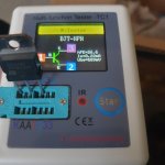
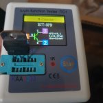
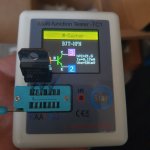
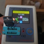
Hi. I found these bjts. But not sure they are genuine. Should output transistors be hfe matched? Please check pictures
Attachments

I have built this amp 7 or so years ago, with bc212, 2n1711 , KD503. Sounded nice !.
2A quiss cureent at 40V supply . Active cooled by a noisy fan tho.
So many variations with 2n1711, 2n1613, BD139.
Wonder how it would "sound" with " modern" transistors. fast output transistors like 2sc/2sa .
I have to read this whole thread !.
- Bruno.
2A quiss cureent at 40V supply . Active cooled by a noisy fan tho.
So many variations with 2n1711, 2n1613, BD139.
Wonder how it would "sound" with " modern" transistors. fast output transistors like 2sc/2sa .
I have to read this whole thread !.
- Bruno.
Veysel -
hard to tell. Can't quite make out the device type number. Seems to say BD240C is that right?
BD240 is PNP, but it might be a BD243?
Anyway the tester is testing them at low current, which is not much use for a power stage.
What are you planning to do with them? Output power level?
(Not good for driver, fT too low).
Every time I come back to this wonderful thread, I feel like I'm in Groundhog Day.

Good to see continued interest in John Linsley-Hood's work. Geoff Moss' The Class A Amplifier Site is now hosted by Elliott Sound Products in Australia: very interesting to see further developments; well worth a visit for other info. as well.
It is now stuck on a loop. Newbies will ask question about circuit, transistors, etc, without reading nearly 10000 comments where many questions have been answered.Every time I come back to this wonderful thread, I feel like I'm in Groundhog Day.
The only way out would be for someone to extract the points made into a summary document.
Not that is really necessary - just reading the original article and follow-ups covers most of them.
- Home
- Amplifiers
- Solid State
- JLH 10 Watt class A amplifier