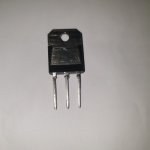
Veysel - BD249C is a TIP35C equivalent. Should be good for 10W class A but these old high current devices had poor second breakdown limit, (35V) not really usable at their rated voltage (100V for C type), but probably OK for 60-70V rails in up to 50W Class AB.
Are you able to check breakdown voltage (needs to be done carefully). Checking devices for datasheet conformance (fake) is a harder tast than just measuring gain.
Output power level was meant to be a question. What output power are you planning?
Are you able to check breakdown voltage (needs to be done carefully). Checking devices for datasheet conformance (fake) is a harder tast than just measuring gain.
Output power level was meant to be a question. What output power are you planning?

Tried Toshiba 2SC5200s ,made for a very "Bright" sounding amp., not surprising as the OP was still flat at 250KHz.!
Beware of fake 5200s, there have been several posts about fakes on the market.
Beware of fake 5200s, there have been several posts about fakes on the market.
Hello everyone, I built my amplifier with the 2SC5200.
Circuit Diagram:
https://drive.google.com/drive/folders/1hqNqf1LpdyNb26nMPSwo5KOk3z-7M26V
Amplifier I built
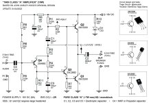
JLH 1969 (10W) per channel - monoblock
PURE "CLASS A" monoblock amplifier
6 ohm speaker
Power: 18V DC
I Q. (BIAS) = 2A
Based on Electronics Engineer John Linsley-Hood's 1969 circuit.
Tests with the amplifier:
https://youtube.com/playlist?list=PLceAdLTPocSHFkuiKAzEND4Blkb3-oGuQ&si=jT_TGq-EO3Z1fZsL
Circuit Diagram:
https://drive.google.com/drive/folders/1hqNqf1LpdyNb26nMPSwo5KOk3z-7M26V
Amplifier I built
JLH 1969 (10W) per channel - monoblock
PURE "CLASS A" monoblock amplifier
6 ohm speaker
Power: 18V DC
I Q. (BIAS) = 2A
Based on Electronics Engineer John Linsley-Hood's 1969 circuit.
Tests with the amplifier:
https://youtube.com/playlist?list=PLceAdLTPocSHFkuiKAzEND4Blkb3-oGuQ&si=jT_TGq-EO3Z1fZsL
Attachments
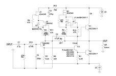
Hi.Thanks for schematic. 2sc2682 is hard to find.Any alternatives? And i hope it not oscillates because of high ft of 2sc5200Hello everyone, I built my amplifier with the 2SC5200.
Circuit Diagram:
https://drive.google.com/drive/folders/1hqNqf1LpdyNb26nMPSwo5KOk3z-7M26V
Amplifier I built
JLH 1969 (10W) per channel - monoblock
PURE "CLASS A" monoblock amplifier
6 ohm speaker
Power: 18V DC
I Q. (BIAS) = 2A
Based on Electronics Engineer John Linsley-Hood's 1969 circuit.
Tests with the amplifier:
https://youtube.com/playlist?list=PLceAdLTPocSHFkuiKAzEND4Blkb3-oGuQ&si=jT_TGq-EO3Z1fZsL
Otherwise, the version without the output capacitor sounds much better and you can easily reach a much higher output power.Is there less love for the version without capacitor output coupling, I see many post on the low powered version
This is my latest version, the output transistor has fT of almost 80Mhz (Y rank) at 2A, C4 is only needed with 2SC1941 which has the lowest Cob of all listed. Soon I plan to make a version with even better CCSs.
Attachments
There are some kits on aliexpress. One of them has njw transistors for output. Are they genuine? Because their prices on mouser digikey are equal or more than the kit itself. Maybe they are genuine but rejected by factory ones? Because they share the inside waffle and it seems good.
I just remember that producing fake of some components are more expensive than buying it. Maybe Njw ones were tested and failed ones by factory. I have already received kit with ktd718 ones and they seem genuine. Sometimes they produce large amounts of components and sold as overstock
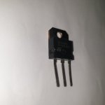
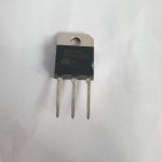
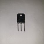
Hi. 10w/pc is enough for me. But for 4 ohm speakers. Here is Bd249c photos. RegardsVeysel - BD249C is a TIP35C equivalent. Should be good for 10W class A but these old high current devices had poor second breakdown limit, (35V) not really usable at their rated voltage (100V for C type), but probably OK for 60-70V rails in up to 50W Class AB.
Are you able to check breakdown voltage (needs to be done carefully). Checking devices for datasheet conformance (fake) is a harder tast than just measuring gain.
Output power level was meant to be a question. What output power are you planning?
Attachments
What about comparing sound quality of 69 amp bridged with phase splitter to eliminate output caps Vs jlh 2003 amp? Which will sound better? I just want to build it with best sound quality. I am obsessive
Last edited:
I also built an Hiraga , found it sounded rather "woolly" compared to the J L-H. Speakers were Rogers Pro9-TLs
Since the ear perceives differences, an SE also sounds theoetically cleaner and more accurate. And even just ONE power supply is cleaner and more accurate than two, or four, or any number of them. If the sound of, for example, complementary push-pull amplifiers with dual PS is somehow cleaner and more accurate, then you have really big problems in terms of loudspeakers, sources, room, placement, other equipment...-)
Hi,
Does the capacitor connected in series to the 2200mf 35v output in the schematic. protect the speaker? Also, is there a need for speaker protection?
Thank you.

Does the capacitor connected in series to the 2200mf 35v output in the schematic. protect the speaker? Also, is there a need for speaker protection?
Thank you.
The capacitors function is to block DC and is needed because the JLH is a single rail design. Indirectly it protects the speaker. AC coupled amps are generally considered speaker safe. No need for any additional speaker protection.
Hi all, just for laughter, I present you the WORST ever JLH Amp clone layout.
It was my first more serious Amp that I bought from some diy'er in late 80's, I was 19 then.
It had a lot of mains buzz and I "fixed" it with capacitors found on scrapyard.
Front pannel design was due to me and my student girlfriend at time being closed in student room for a while, can't remember what exactly we consumed then, but results talk for themselves 🤣.
Probably from sentimental reasons I still drag it in my garage.
Lol, Drazen
😳 but 🙂
You were not very far from a painting by Claude Monet called "the artist's garden at Giverny"

You were not very far from a painting by Claude Monet called "the artist's garden at Giverny"
Thank you, very kind of youYou were not very far from a painting by Claude Monet called "the artist's garden at G
Not sure what you are saying there. It is more the type of transistor than whether it is in a TO-264 case or not.For JLH-69 better to use something in TO-264 or TO-3, or build JLH 1996/2001 (2003) with dual PS.
😛
The BD249 has an ft of 3MHz and 125W power rating. In a JLH it should be fine -the second breakdown starts at 30V, but OK for 10W I would think.
It was originally in a TO-218 case, but newer versions (TIP35C?) seem to be shipped in TO-247.
I think the avoidance of capacitor coupling is over-rated. Modern capacitors with low ESR and ESL should be good. I would strongly recommend using larger capacitors than the 1970's standard value of 2.2mF. Something like 15 or 22mF will provide far better bass response.
Though if someone has distortion measurements of modern capacitors to show that they distort that may persuade me to change the recommendation.
The point is that the voltage across the capacitor, in use, should not change. If the capacitor is not mechanically rigid then high currents might created magneto-induced movement which might increase distortion, but I did not measure any worse distortion on an old Class AB design using what are now 30year old 2000uF caps. (And that was <0.02% at 20kHz, 50W). Maybe they were better built then but I somehow doubt it.
- Home
- Amplifiers
- Solid State
- JLH 10 Watt class A amplifier